Scan pages 9–13
Transport Mechanism & Adjustment
V. Transport Mechanism
Driving of Capstan
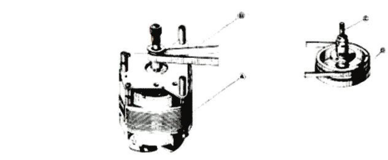 ⤢ zoomMotor and flywheel assembly for the capstan drive, with driving belt and mounting screws called out
Fig. 1
Figure 1.
- (A) Motor
- (B) Driving Belt (flat belt)
- (C) Capstan
- (D) Flywheel
High-speed rotation of Motor (A) is reduced by Driving Belt (B) and transmitted to Capstan (C), which is connected of flywheel with ample inertia and enables rated rotation by absorbing minor rotation distortion of motor itself.
Capstan Rotation:
- 606 R.P.M. at 7-1/2" (19 cm) per sec.
- 303 R.P.M. at 3-3/4" (9.5 cm) per sec.
- 151.5 R.P.M. at 1-7/8" (4.75 cm) per sec.
Motor Rotation:
- 3,000 to 1,500 R.P.M. at 50 cps.
- 3,600 to 1,800 R.P.M. at 69 cps.
Driving of Pinch Wheel
Put tape between rotating capstan and pinch wheel and push pinch wheel against capstan, this will transport the tape at rated speed. The appropriate pressure of pinch wheel is between 1,000 to 1,150 grams at the tape speed of 7-1/2" (19cm) per second.
Recording and Playback
Turn the RECORD/PLAYBACK KNOB (A) to "PLAY" position, and pinch wheel presses against capstan to move tape at the rated speed. At the same time, Idler (B) moves between Motor Bushing (C) and the Take-Up Reel Spindle (D) to transmit the motor rotation to (D) so that the tape is moved and wound on the take-up reel.
The Take-up Reel Spindle Base is made up of two plastic rollers (1 and 2) with a clutch felt in between. The Idler is rotating the plastic roller (2) under. Therefore, the tape-winding friction is adjusted by the slipping of the felt to enable rated winding of the tape.
On the other hand, the Supply Reel Spindle (H) has a Brake Roller (E) hung on the Plastic Roller 4 under which provides appropriate back tention by the clutch felt slipping to the rotation of the Pulley (3) above.
To prevent accidental erasure, the Record Interlock Button (F) must be depressed before the RECORD/PLAYBACK KNOB can be moved to the "REC" position. The Safety device (G) is depressed to enter the record mode.
(See figure 2)
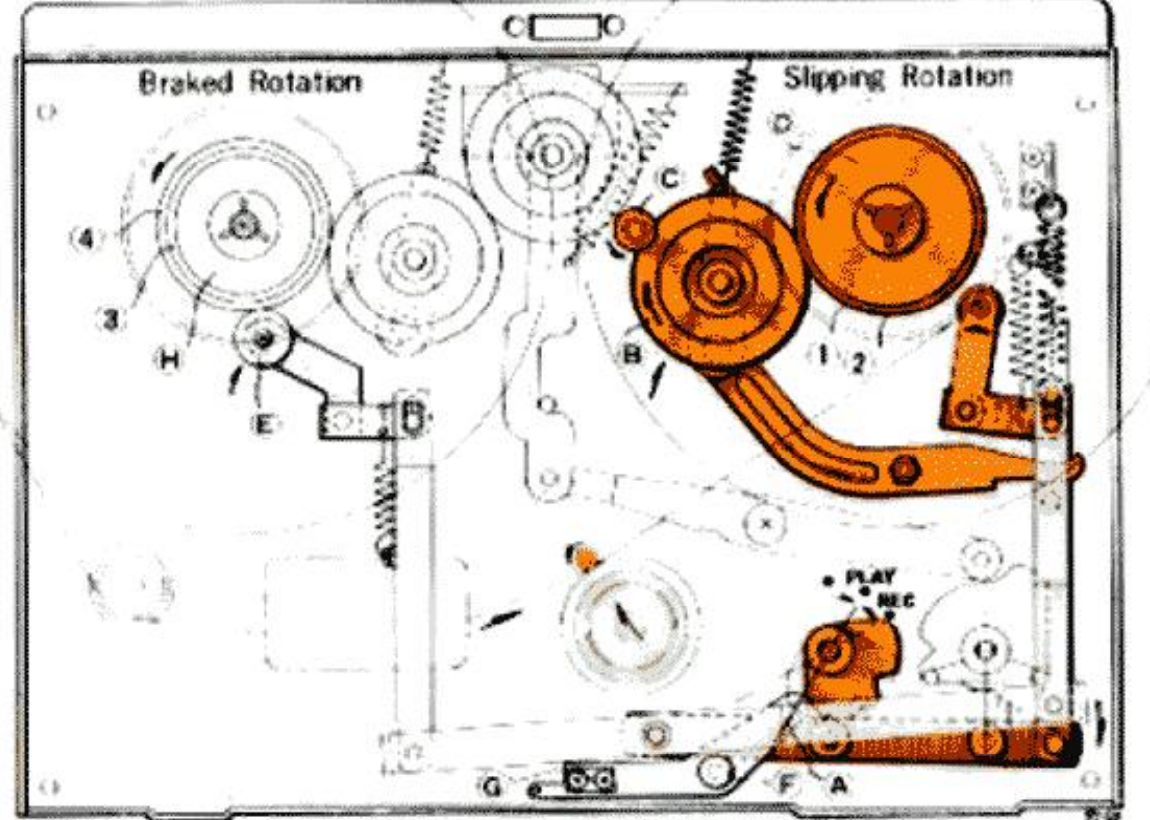 ⤢ zoomRecording/playback engagement diagram: Idler (B) between Motor Bushing (C) and Take-Up Reel Spindle (D) on the slipping-rotation side; Brake Roller (E) on Plastic Roller 4 and Pulley (3), Supply Reel Spindle (H), on the braked-rotation side
Fig. 2
Fast-Forward Mechanism
Turn the FAST FWD-REWIND knob (A) to "FAST FWD" position, and the cam (B) under the knob pushes up the Lever (C). The Idler (D) moves into the space between the Plastic Roller (F) above the Take-Up Reel Spindle and the upper part of the rotating motor drive bushing to transmit the motor rotation to the take-up reel spindle. At the same time, Brake Rollers (H) and (I) come off the reel spindle to free the Supply Reel Spindle (G), thereby allowing fast winding of the tape onto the take-up reel.
(See figure 3)
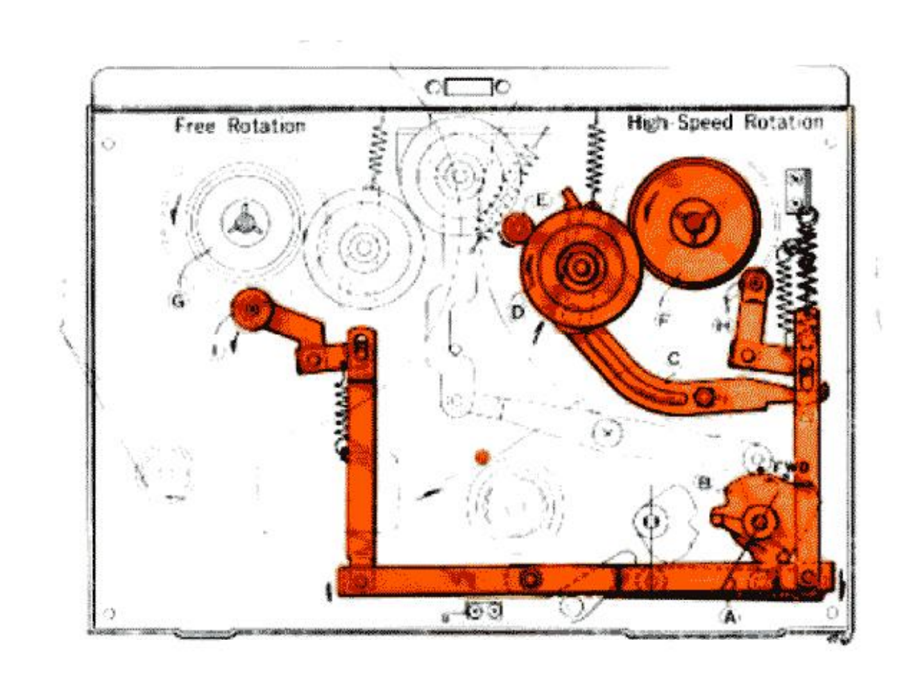 ⤢ zoomFast-forward mechanism diagram, free rotation at left and high-speed rotation at right, with idler, cam, lever, and brake roller linkage called out
Fig. 3
Rewind Mechanism
Turn the FAST FWD-REWIND knob (A) to "REWIND" position, and the cam (B) under the knob pushes the Lever (C) up. The Idler (D) moves into the space between the upper part of the rotating Motor drive bushing (E) and the Intermediate Pulley (F) to transmit the high-speed rotation of the motor through the intermediate pulley to the Supply Reel Spindle (G). At the same time, Brake Rollers (H) and (I) come off the reel spindle to free the take-up reel spindle (J), thereby rewinding the tape into the supply reel at a fast speed.
(See figure 4)
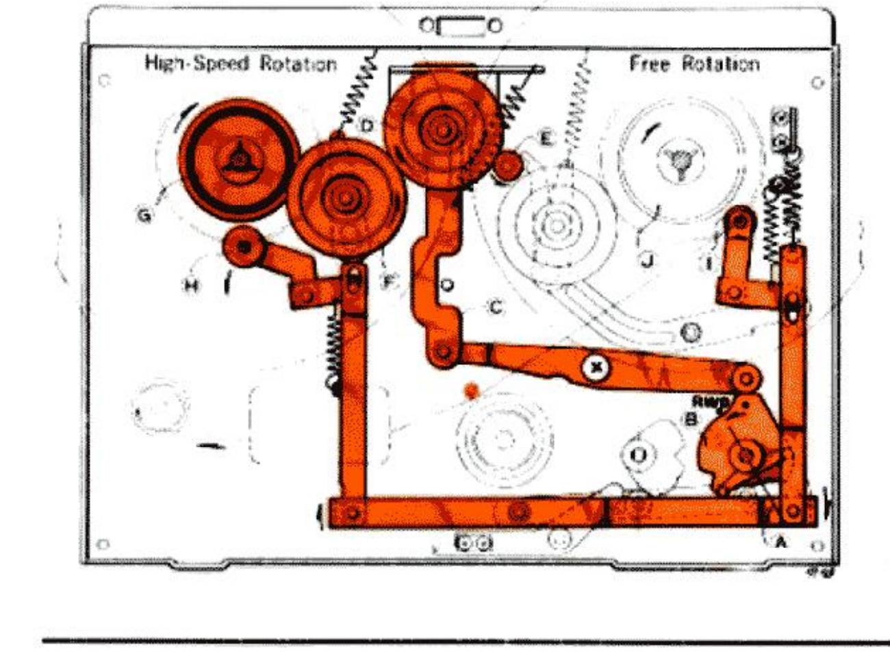 ⤢ zoomRewind mechanism diagram, high-speed rotation at left and free rotation at right, with idler, cam, lever, and intermediate pulley linkage called out
Fig. 4
Stop Control
Push the stop lever to "STOP" position, Brake Rollers (A) and (B) depress reel spindles to stop rotation of the reel spindles.
As the brake rubber depresses the plastic rollers under the reel spindles, no friction works on the tape itself.
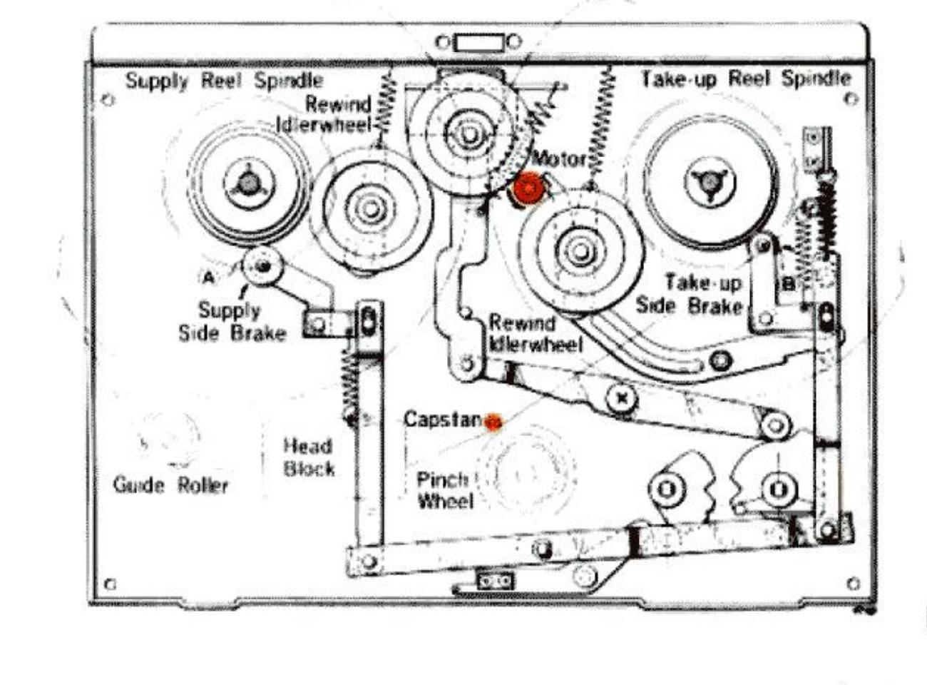 ⤢ zoomStop control diagram of the deck, with supply and take-up reel spindles, capstan, pinch wheel, head block, and both brake rollers labeled
Fig. 5
Modes of Operation
| Modes of Operation | Pinch Wheel | Take-up Idler Wheel | Rewind Idler Wheel | Take-up side Brake | Supply side Brake |
|---|---|---|---|---|---|
| (a) STOP | × | × | × | ○ | ○ |
| (b) FAST-FORWARD | × | ○ | × | × | × |
| (c) REWIND | × | × | ○ | × | ○ |
| (d) RECORDING PLAYBACK | ○ | ○ | × | × | × |
NOTES: ×-marks indicates "open" and
○-marks "engaged"
Record/Playback Changing Mechanism
By turning the RECORD/PLAYBACK KNOB (N) to the recording position, the LEVER (a) pushes the RECORDING LEVER (b) and (c), as illustrated in dotted line, then the RECORD/PLAYBACK CHANGING SWITCH (SWI) turns to recording position.
If the LEVER (b) does not push the LEVER (c) properly, the SWI does not operate properly so may occur the abnormal oscillation and also can't record.
Then must adjust the LEVER (b) to proper position by loosing the SCREW (d).
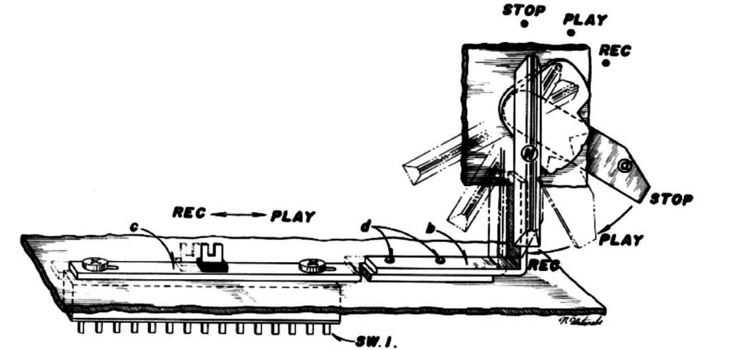 ⤢ zoomRecord/playback changing mechanism: the knob assembly (N) with STOP, PLAY, and REC detents, linked to switch levers b, c, and d that drive switch SW.1
Fig. 6
VI. Mechanism Adjustment
1. Adjustment of Pinch Wheel
It is important that the pinch wheel shaft is kept in complete alignment with the capstan shaft. A proper pinch wheel pressure is between 1,000 and 1,150 grams when the unit is operated at the tape speed of 7-1/2 ips. Any deviation from this specification will result in wow and flutter. Check pinch wheel pressure by a spring scale, and if necessary, adjust the pinch wheel load spring.
2. Adjustment of Take-Up Idler Wheel
The take-up idler wheel must be kept in complete alignment with the take-up reel shaft. When the unit is set in fast forward condition, the idler wheel will contact to the upper knurled wheel of the take-up reel shaft assembly, and it will contact to the lower knurled wheel during record or play mode. Adjust idler wheel load spring so that the idler wheel pressure is kept between 50 and 80 grams. The idler wheel rapidly wears if the pressure is excessive. The slippage occurs if the pressure is smaller than the specification.
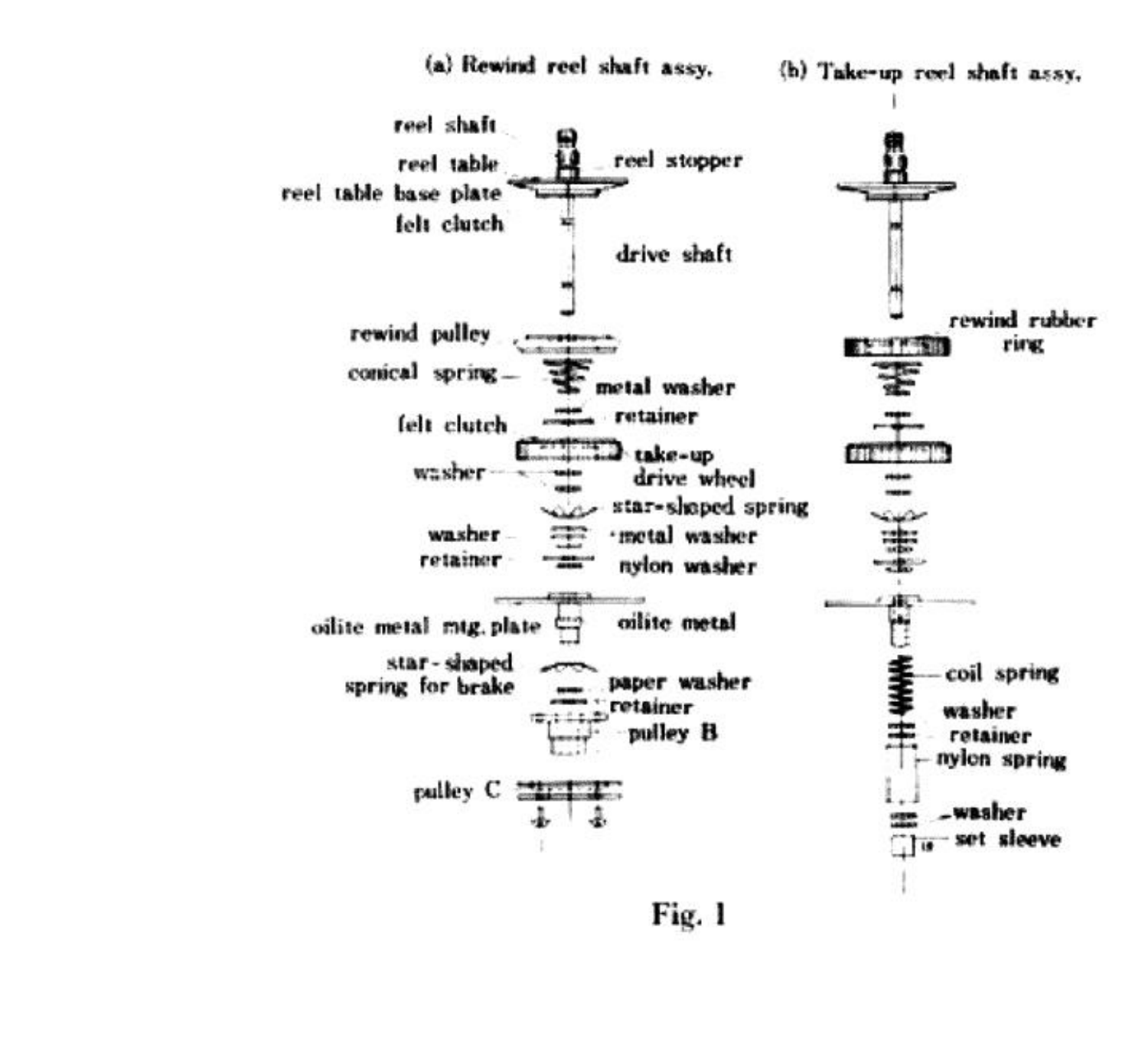 ⤢ zoomCutaway diagrams of the rewind reel shaft assembly (a) and take-up reel shaft assembly (b), stacked component labels from reel shaft down to pulley C / set sleeve
Fig. 1
3. Adjustment of Rewind Idler Wheel
The rewind idler wheel must be kept in complete alignment with the rewind reel shaft. The amount of pressure to the knurled motor bushing should be maintained about 50 grams during rewind operation. Adjust both the idler load spring and rewind roller.
4. Adjustment of Intermediate Wheel
The intermediate wheel is located between the rewind idler wheel and the rubber ring which is used on the upper part of the supply reel shaft assembly. When the unit is set in rewind mode, it will contact to these parts simultaneously delivering torque of motor. An adequate pressure is 50 grams. Adjust the load spring of the intermediate wheel if the pressure is not sufficient.
5. Adjustment of Take-Up Reel Shaft Assembly
A felt clutch material is attached to the bottom side of the reel table base plate so that recording tape will not be stretched during fast forwarding operation due to excessive tension. To check the amount of friction of this part, place a 5-inch reel with recording tape wound by 60 m/m in diameter, and gently pull the end of tape upward using a spring scale. Adjust the conical spring so that the amount of tension at this part will be kept between 400 to 500 grams. Another felt clutch material is attached to the take-up drive wheel. It is to provide proper slipping operation during record or play mode. The procedure for checking friction of this part is same as the foregoing, and between 150 and 200 grams of friction will provide the best result. Adjust the star-shaped spring just under the take-up drive wheel. When the unit is set in rewind mode, the amount of friction of this part will greatly be reduced and will become 15 to 20 grams. Check to see whether this is satisfactory if not, readjust the star-shaped spring for Brake, and spring retainer washed accordingly. (See figure 1 (b) at left)
6. Adjustment of Supply Reel Shaft Assembly
A felt clutch material is used between the lower side of the reel table base plate and the rewind rubber ring to protect recording tape from an excessive tension while rewinding operation. To check the amount of friction of this part, place onto the supply reel table a 5-inch reel with recording tape wound by 60 m/m in diameter and gently pull the end of tape upward by a spring scale. Adjust the conical spring so that the amount of tension is kept between 400 and 500 grams. Another felt clutch is attached to the rewind drive wheel to provide proper slipping operation during record or play mode. The procedure for checking friction of this part is same as the foregoing, and between 80 and 120 grams of friction will give the best result. When the unit is set in fast forward mode, the amount of friction will greatly be reduced and will become 15 to 20 grams.
Check to see whether this is proper, if not, readjust coil spring and spring retainer washer. (See figure 1 (a) at left)
7. Adjustment of Head
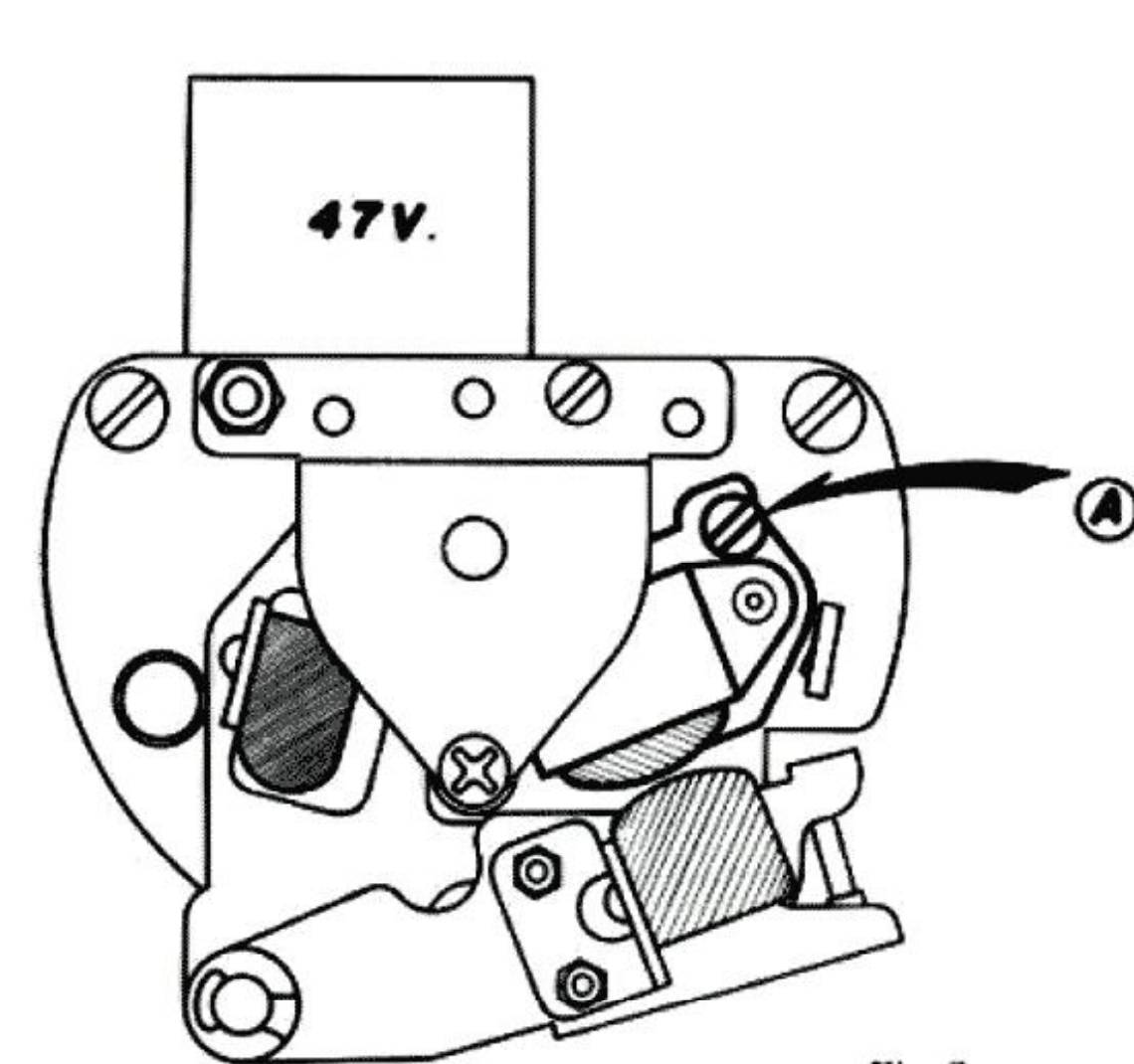 ⤢ zoomRecording/playback head assembly, screw driver access from the top with the azimuth adjustment screw (A) called out and a "47V." reference label above the head
Fig. 2
a) Playback 8,000 cps recorded tape and set the azimuth alignment of the Recording/Playback Head by turning the screw (A) until the voltage of the Line Output or the VU meter reads at a maximum.
b) Adjustment of Head Level.
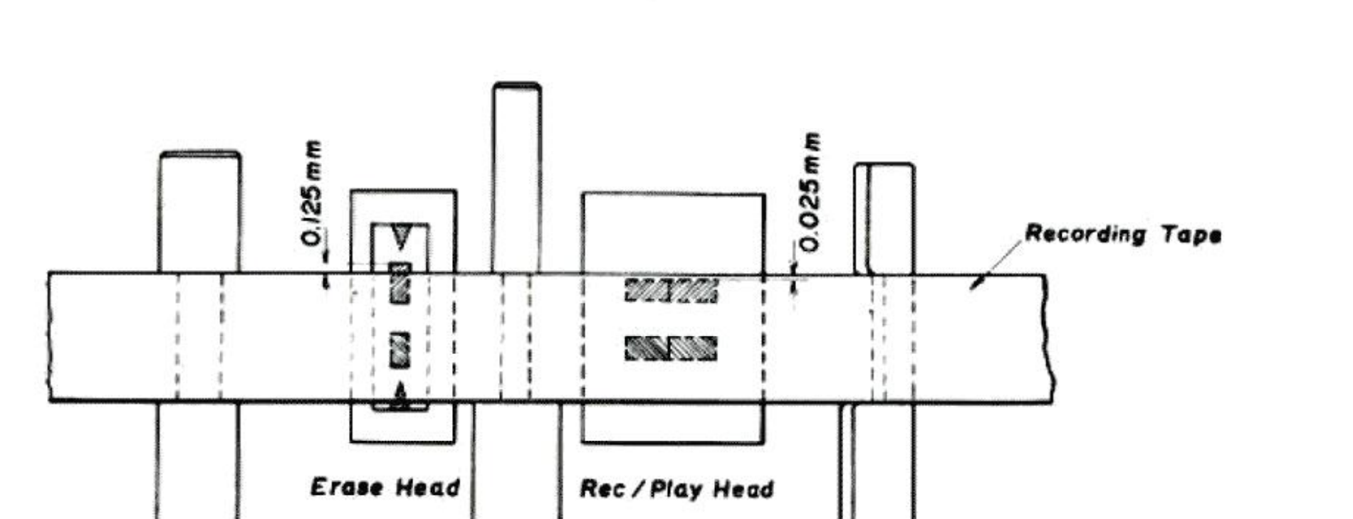 ⤢ zoomSide elevation of the tape path showing the Erase Head and Rec/Play Head gap heights relative to the recording tape: 0.125mm and 0.025mm dimensions called out
Fig. 3
- Position the Erase Head about 0.125 mm above the upper edge of the tape by adjusting the height of the cam provided in the lower part of the head assembly.
- Adjust the position of the Recording/Playback Head in a manner illustrated in figure 3 by adjusting the level control nut (A) at the lower part of the head assembly.