Scan pages 14–16
Amplifier Adjustment & Maintenance
VII. Amplifier Adjustment
1. Adjustment of Recording Bias Frequency
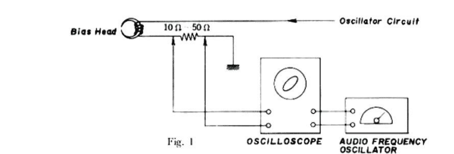 ⤢ zoomBlock diagram: Bias Head connected through a 10 Ω–50 Ω resistor to the oscilloscope's vertical input, the oscillator circuit feeding the oscilloscope's horizontal input, and the audio frequency oscillator supplying the oscillator circuit
Fig. 1
a Connect the resistor (10 Ω or 50 Ω) in series with the bias head, and connect the signal from the resistor to the vertical input of the oscilloscope.
The output of the audio frequency oscillator should be connected to the horizontal input of the oscilloscope.
Proper Bias frequency of the recorder X-150D is obtained when the oscilloscope displays a circular or linear waveform with the frequency of the audio frequency oscillator in the neighbourhood of 60 kc/s.
The frequency of the bias oscillator circuit can be adjusted by converting the value of the condenser (C 18. 10,000 PF).
2. Adjustment of Recording Bias Voltage
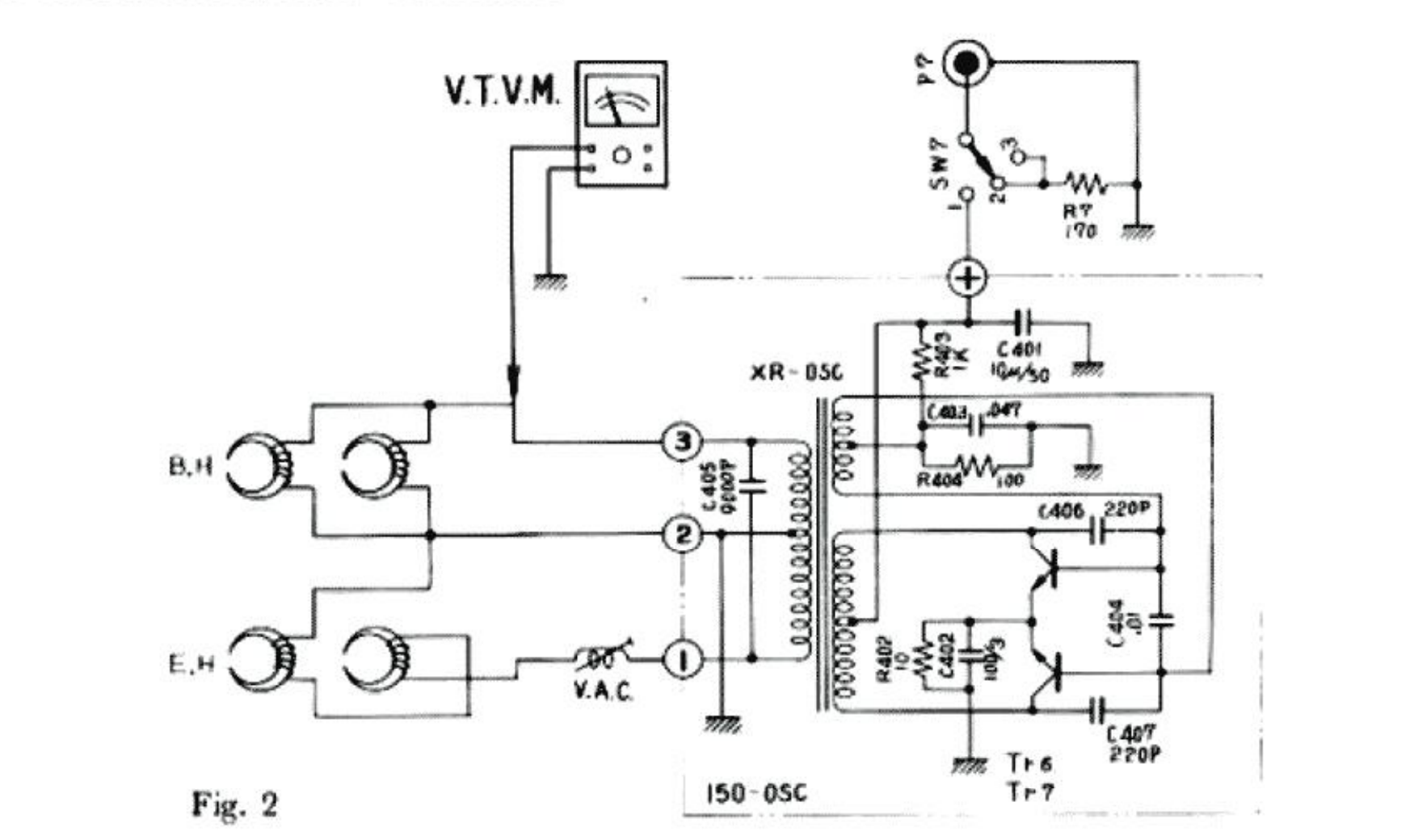 ⤢ zoomBias oscillator circuit schematic: V.T.V.M. connected to the bias head (B.H) and erase head (E.H) windings through a V.A.C. switch and terminals 1–3, feeding transformers XR-OSC/150-OSC and oscillator transistors Tr6/Tr7
Fig. 2
a) Connect the V.T.V.M. to the bias head and fix the recording bias voltage by adjusting the V.A.C in the bias oscillator circuit (located near the head assembly) until its readings becomes equal to the bias voltage stamped backside the head assembly.
Normal bias voltage is between 60 V and 70 V, while acceptable terminal voltage of the erase head is between 12 V and 18 V.
3. Adjustment of Playback Gain
a) Playback 0 VU tape recorded with 1,000c/s signal information and adjust the semi-fixed resister VR201 (20KΩB) of the preamplifier card so that the pointer of the VU meter registers on 0 VU (intermediate between red and black).
b) When performing the above adjustments, make sure that the equalization switch has been set in coincidence with the speed of the tape.
4. Adjustment of Recording Level
a) The recording level should be adjusted after the playback gain has been adjusted in the manner described.
b) Set a standard tape (SCOTCH-111) on the recorder X-150D and put it in a recording mode of operation.
c) Connect the signal of 1,000c/s from the audio oscillator to the line input of the recorder X-150D, and adjust the volume control so that the pointer of the VU meter registers on 0 VU (intermediate between red and black).
d) Now record the tape and check on playback whether the pointer of the VU meter comes on the 0 VU point.
e) If the pointer of the VU meter fails to register with 0 VU, repeat the recording and playback by adjusting the semi-fixed register VR 161 (2KΩB) of the recording preamplifier until the 0 VU reading is obtained both on recording and playback.
VIII. Maintenance Procedures
1. Lubrication Instruction
For maximum service life and optimum performance, lubricate the parts identified below after each 500 hours of operation. Use only light machine oil of good quality.
| Part | Amount |
|---|---|
| Motor | |
| Flywheel Assembly | |
| Rewind Idler Wheel and Wind Take-Up Idler | 1 drop |
| Intermediate Idler | 1 drop |
| Pinch Wheel | 1 drop |
Also apply a liberal film of light machine grease to each roller surface of all levers and cams.
CAUTION : DO NOT OVER-LUBRICATE, AND WIPE OFF EXCESS OIL BY A COTTON SWAB SOAKED IN ALCOHOL. OTHERWISE, THE OVER-FLOWED LUBRICANT MAY BE SCATTERED DURING OPERATION. THE RUBBER COMPONENT PARTS WILL BE DETERIORATED.
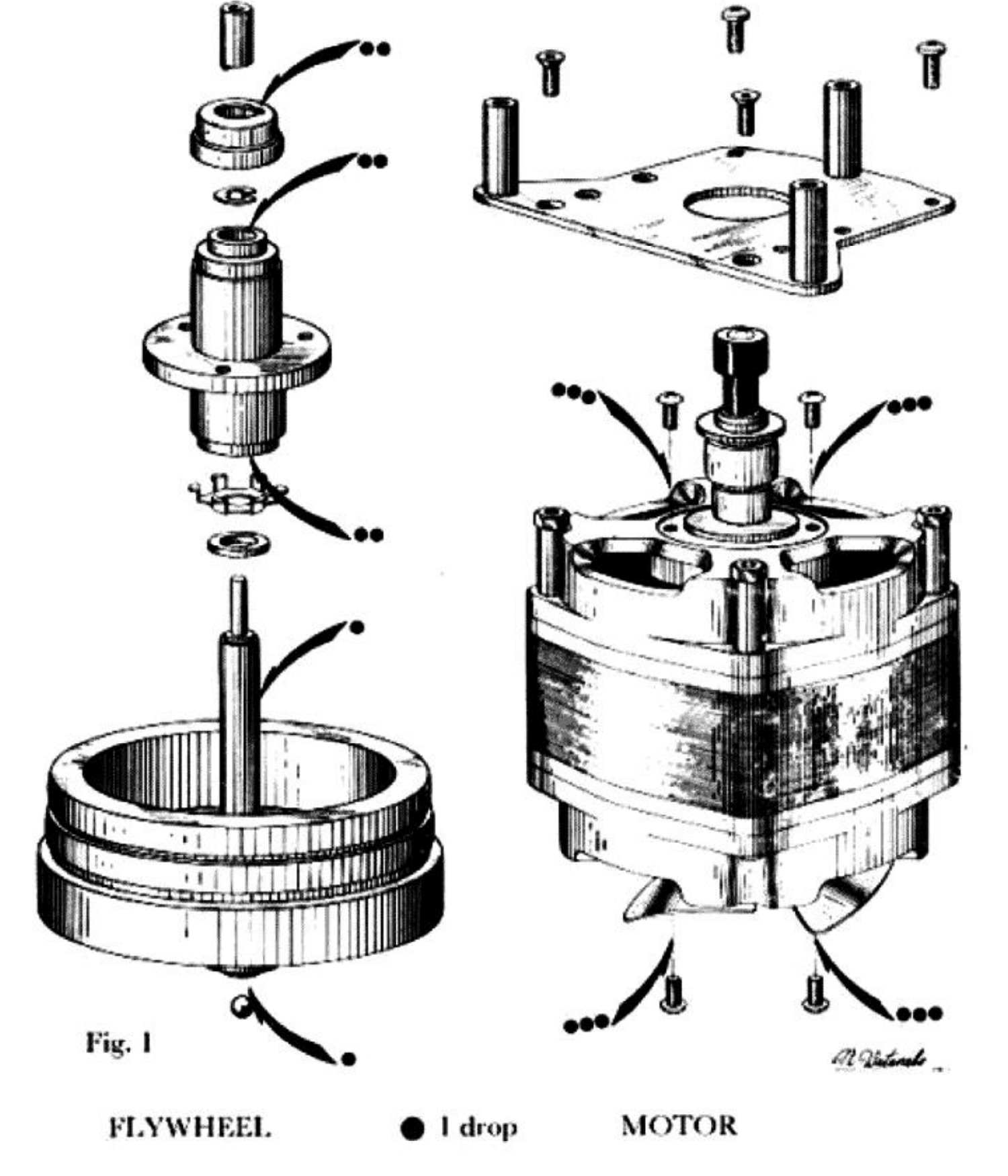 ⤢ zoomExploded view of the flywheel assembly (left) and motor (right), lubrication points marked with dots keyed to the "1 drop" legend
Fig. 1
FLYWHEEL ● 1 drop MOTOR
2. Cleaning Tape Heads and Other Parts
Wipe surface of tape heads, guide roller bearing, capstan bushing and pinch wheel periodically with a soft cloth soaked in alcohol or carbon-tet.