Scan pages 7–8
Disassembly
IV. Disassembly of Tape Transport Unit & Amplifiers
-
Loosen the RETAINING SCREW (a) of PINCH WHEEL (b) using a phillips-headed screw driver and remove the PINCH WHEEL by hand.
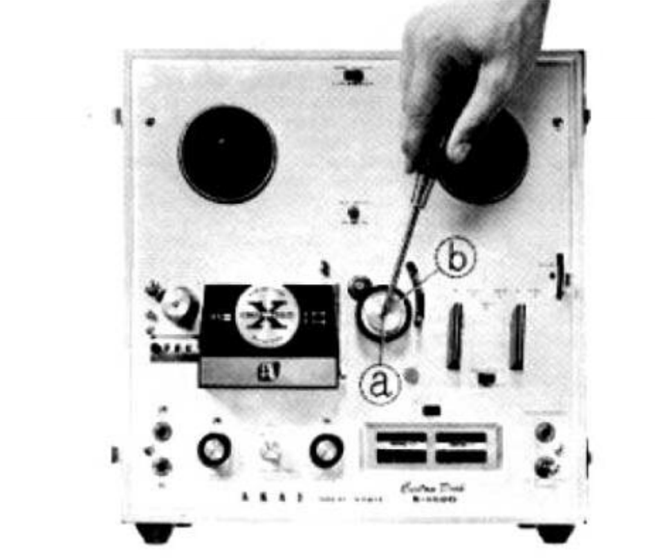 ⤢ zoomRemoving the pinch wheel (b) after loosening its retaining screw (a)
 -
Loosen the RETAINING SCREW (a) of the TRACK SELECTOR KNOB (b) using a phillips-headed screw driver and remove the TRACK SELECTOR KNOB by hand.
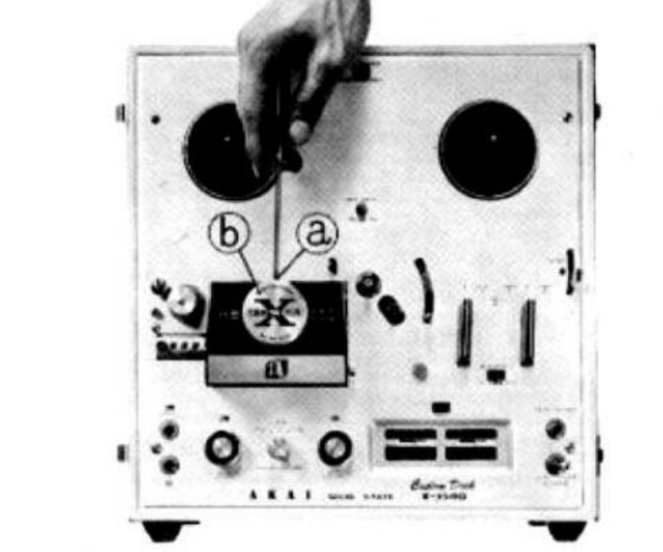 ⤢ zoomRemoving the track selector knob (b) after loosening its retaining screw (a)
 -
Loosen the RETAINING SCREWS of the KNOBS ((a), (b) and (c)) by using a minus-headed screw driver and remove the KNOBS by hand.
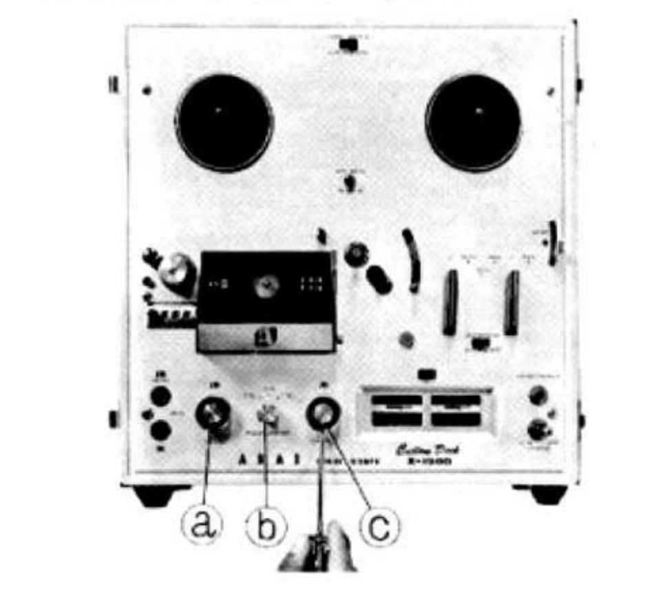 ⤢ zoomRemoving the front panel knobs (a), (b) and (c) with a minus-headed screw driver
 -
Loosen the RETAINING SCREWS of the DECK CONTROL KNOBS ((a) and (b)) by using a phillips-headed screw driver and remove the KNOBS by hand.
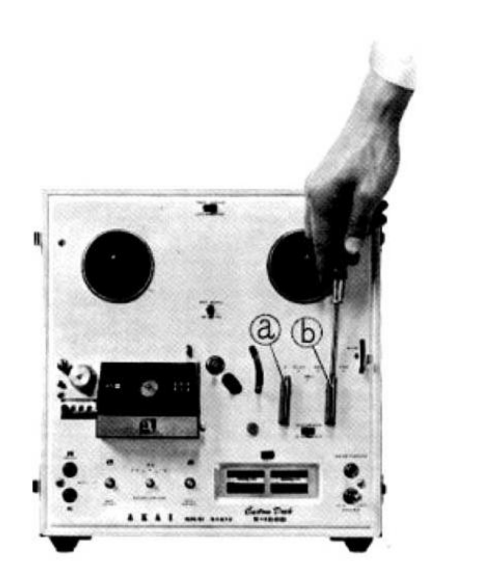 ⤢ zoomRemoving the deck control knobs (a) and (b)
 -
Loosen the SCREWS (marked from (a) to (d)) by using a phillips-headed screw driver and remove the DECK PANEL by hand.
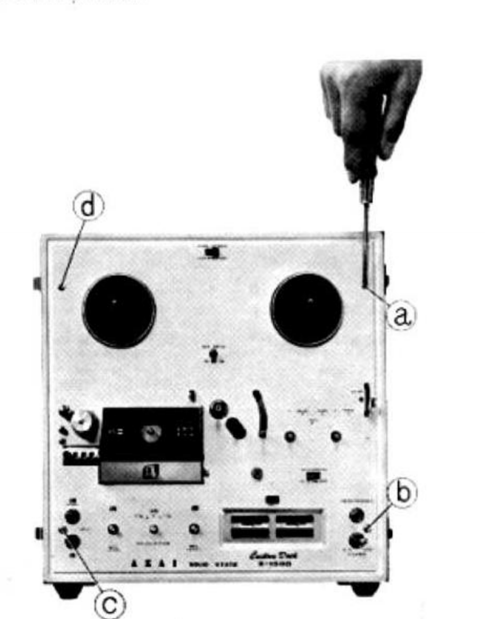 ⤢ zoomRemoving the deck panel after loosening screws (a) to (d)
 -
Loosen the SCREWS (marked from (a) to (d)) by using a phillips-headed screw driver.
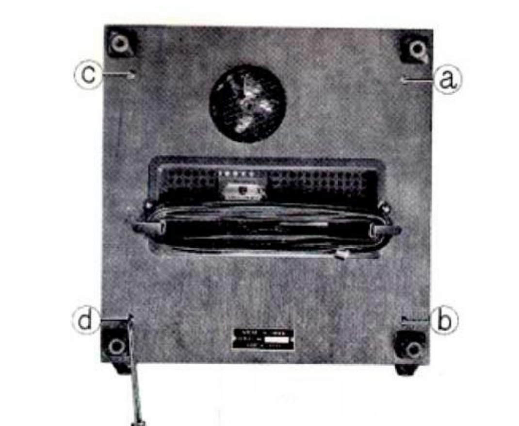 ⤢ zoomThe case back, with corner screws (a) to (d) circled
 -
Loosen the SCREWS (marked from (a) to (d)) by using a phillips-headed screw driver.
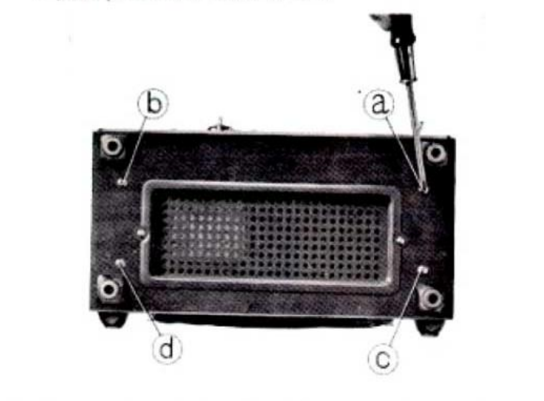 ⤢ zoomThe case's perforated bottom panel, with corner screws (a) to (d) circled
 -
Remove the TAPE TRANSPORT MECHANISM ASSEMBLY and AMPLIFIER ASSEMBLY (A) by slowly lifting it from the CASE (B) as shown in picture.
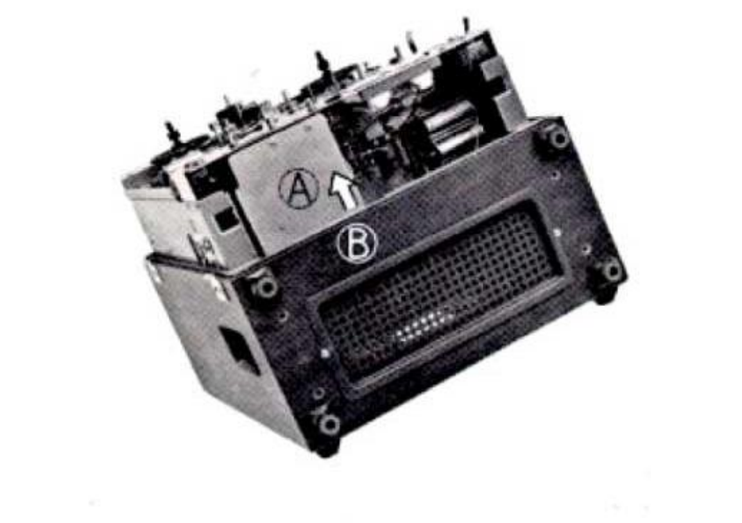 ⤢ zoomLifting the tape transport mechanism and amplifier assembly (A) from the case (B)
 -
Disconnect the PLUGS marked (a) to (d) carefully by hand.
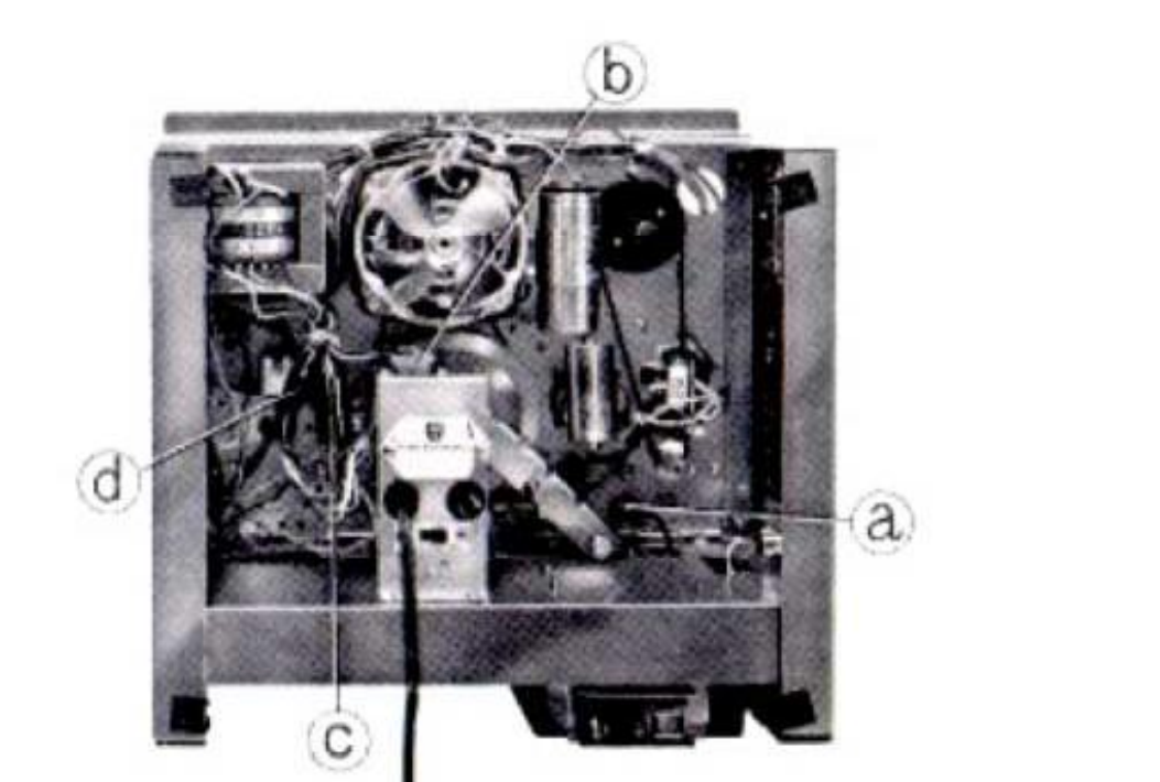 ⤢ zoomDisconnecting plugs (a) to (d) inside the amplifier assembly
 -
Loosen the SCREWS (marked from (a) to (d)) of the DECK FRAME by using a phillips-headed screw driver.
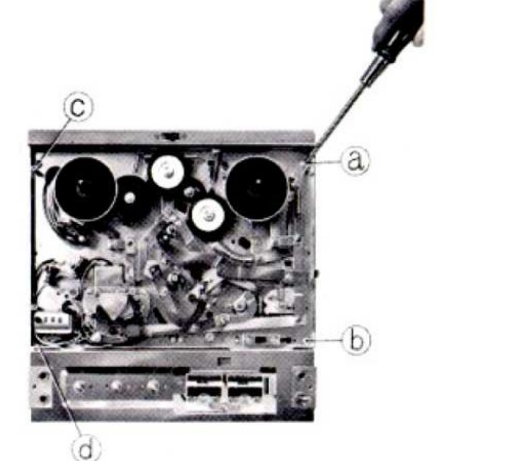 ⤢ zoomThe deck frame, with screws (a) to (d) circled
 -
Separate the TAPE TRANSPORT MECHANISM ASSEMBLY (B) from AMPLIFIER ASSEMBLY (A) carefully by hand.
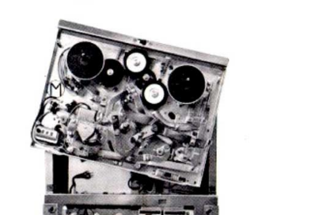 ⤢ zoomSeparating the tape transport mechanism assembly (B) from the amplifier assembly (A)