⤢ zoomSchematic sheet 1: the four-track cross-field head assembly (No. 7) with its record/playback, bias, and erase head switching, feeding the CD-512 record/playback amplifier board (Tr1–Tr4) and the CD-511 board, wired to the microphone and line input jacks, line outputs, stereo phones jack, VU meters, and DIN connectors
⤢ zoomSchematic sheet 2: the bias oscillator section (XR-OSC and 150-OSC transformers, Tr6–Tr7), the power supply with its 100–240 V voltage-selector taps, rectifier diodes, pilot lamp, and motor circuit, plus the factory transistor-type list in the margin and a note that the right-channel P.C. board is the same as the left
Component BOM
Semiconductors
Ref
Schematic
Chapter IX listing
Notes
Tr1, Tr2
2SC650 Ⓐ
Transistor 2SC650 (A) — C9-003a
Tr3, Tr4
2SC281 Ⓑ
Transistor 2SC281 (B) — C9-003b
Tr5
2SC458 Ⓑ
Transistor 2SC458 (B) — C8-006
Tr6, Tr7
2SC696 [suffix illegible]
Transistor 2SC696 — C10-004
The margin list prints circled grade letters after 2SC696 that don't resolve at scan resolution; the specifications chapter's TRANSISTOR USED row and the oscillator board layout's caption (manual p. 22) both print them as (J) (I) (F).
D101
(type not printed)
Diode 1N34A — C8-005
D-1, D-2
(type not printed)
Silicon Diode SW-05-01 — C7-017 / C10-007
Rectifier pair off T1's secondary.
CD-512 record/playback amplifier card
Ref
Schematic
Chapter IX listing
Notes
R201
100K
Resistor 1/4P 100KΩ J — C9-004f
R202
100K
Resistor 1/4P 100KΩ J — C9-004f
R203
150K
Resistor 1/4P 150KΩ K — C9-004h
R204
3.3K
Resistor 1/4P 3.3KΩ K — C9-004b
R205
220
Resistor 1/4P 220Ω K — C9-004a
R206
22K
Resistor 1/4P 22KΩ K — C9-004d
R207
4.7K
Resistor 1/4P 4.7KΩ K — C9-004c
R208
100K
Resistor 1/4P 100KΩ J — C9-004f
R209
120K
Resistor 1/4P 120KΩ J — C9-004g
R210
10K
Resistor 1/4P 10KΩ K — C9-004m
R211
4.7K
Resistor 1/4P 4.7KΩ K — C9-004c
R212
15K
Resistor 1/4P 15KΩ K — C9-004n
R213
470
Resistor 1/4P 470Ω K — C9-004k
R214
100
Resistor 1/4P 100Ω K — C9-004i
Chapter IX prints this designator as "(R) 214)".
R215
1.5K
Resistor 1/4P 1.5KΩ K — C9-004l
R216
330
Resistor 1/4P 330Ω K — C9-004j
R217
68K
Resistor 1/4P 68KΩ J — C9-004e
VR201
20KB
Variable Resistor 20KB — C9-006
Playback-gain preset — chapter VII's procedure sets it against a 0 VU reference tape until the VU meter reads 0 VU.
C201
10/10
Condenser 10μ 10V — C9-005b
C202
10/10
Condenser 10μ 10V — C9-005b
C203
50/25
Condenser 50μ 25V — C9-005d
C204
10/10
Condenser 10μ 10V — C9-005b
C205
.01
Condenser 0.01μ 50V — C9-005g
C206
10/10
Condenser 10μ 10V — C9-005b
C207
1/10
Condenser 1μ 10V — C9-005i
C208
100/3
Condenser 100μ 3V — C9-005a
C209
100/3
Condenser 100μ 3V — C9-005a
C210
.022
Condenser 0.22μ 50V — C9-005h
Sources disagree: the schematic prints .022 and the CD-512 board layout (manual p. 20) also reads .022; chapter IX's 0.22μ is the odd one out, off by a decade.
C211
330P
Condenser 330P 35WV — C9-005e
C212
10/25
Condenser 10μ 25V — C9-005c
C213
220P
Condenser 220P 35V — C9-005f
T201
(value not printed)
Headphone Transformer 7K 8Ω — C9-007
CD-511 equalizer / head-switching card
Ref
Schematic
Chapter IX listing
Notes
R101
68K
Resistor 1/4P 68KΩ K — C8-008b
R102
22K
Resistor 1/4P 22KΩ K — C8-008c
R103
22K
Resistor 1/4P 22KΩ K — C8-008c
R104
5.6K
Resistor 1/4P 5.6KΩ K — C8-008g
R105
22K
Resistor 1/4P 22KΩ K — C8-008c
R106
10K
Resistor 1/4P 10KΩ K — C8-008f
R107
15K
Resistor 1/4P 15KΩ K — C8-008d
R108
1K
Resistor 1/4P 1KΩ K — C8-008i
R109
120K
Resistor 1/4P 120KΩ K — C8-008a
R110
10K
Resistor 1/4P 10KΩ K — C8-008f
R111
12K
Resistor 1/4P 12KΩ K — C8-008e
R112
27K
Resistor 1/4P 2.7KΩ K — C8-008h
Sources disagree: the schematic clearly prints 27K, but chapter IX and the CD-511 board layout (manual p. 21) both print 2.7K — the schematic is the odd one out, off by a decade.
VR161
2KB
Variable Resistor V-10K5 2KΩ B — C8-009
Chapter IX lists the 2KΩ (B) preset without a designator, and the schematic's and board layout's prints are cramped (VR151 or VR161) — but chapter VII's recording-level adjustment names it in running text: "VR 161 (2KΩB)". Set so 0 VU on recording matches 0 VU on playback.
C101
.15
Condenser 0.15μ 35V K — C8-010j
C102
330P
Condenser 330PF 35V K — C8-010d
C103
.012
Condenser 0.012μ 50V J — C8-010f
C104
120P
Condenser 120PF (J) — C8-010k
C105
.01
Condenser 0.01μ 50V K — C8-010e
C106
.015
Condenser 0.015μ 50V K — C8-010g
C107
.056
Condenser 0.056μ 50V K — C8-010i
C108
3/25
Condenser 3μ 25V — C8-010a
C109
.022
Condenser 0.022μ 50V K — C8-010h
C110
10/10
Condenser 10μ 10V — C8-010b
C111
30/3
Condenser 30μ 3V — C8-010c
C112
220P
—
No chapter IX row, but the CD-511 board layout prints C112 220P — board and schematic agree.
L101
47mH
—
No chapter IX row; the board layout prints the same value.
L102
3mH
—
No chapter IX row; the board layout prints the same value.
SW101
(record/play slide switch)
—
Chapter IX lists card slide switches without a designator; the board layout prints SW101 beside its REC⇄PLAY legend.
Chassis: amplifier and power supply
Ref
Schematic
Chapter IX listing
Notes
R1
680
Resistor 1/4P 680KΩ — C7-013a
Sources disagree: the schematic prints 680 with no K (unlike its neighbor R2 220K); chapter IX lists 680KΩ.
R2
220K
Resistor 1/4P 220KΩ — C7-013b
R3
68K
Resistor 1/4P 68KΩ — C7-013c
R4
910
Resistor 1W L 910Ω — C7-013e
R5
82
Wired Resistor 2W 82Ω — C7-013d
R6
47
—
Schematic only; in the head-shield/DIN circuit at J8.
R7
170
Wired Resistor 5W 170Ω — C4-002a
Chapter IX lists it in the Switch Block without a designator; the schematic supplies R7.
R8
4.7K
Resistor 1/4P 4.7KΩ — C7-013f
R9
15K
Resistor 1/4P 15KΩ — C7-013g
VR1
50KA
Variable Resistor 50KΩ (A) — C7-007
Record-level control.
C1
500/50
Tubular Type Electrolytic Condenser 500μF 50WV — C7-014a
C2
1000/25
Tubular Type Electrolytic Condenser 1000μF 25WV — C7-014b
C5
1µ
—
Motor circuit; schematic only.
C6a
20µ
—
Motor circuit; schematic only.
C6b
0.8µ
—
Motor circuit; schematic only.
HT-1.5
(choke, one per channel)
—
In series with each playback head line; schematic only.
Chapter IX lists the card's three resistors without designators; the schematic supplies them, and the oscillator board layout (manual p. 22) prints the same designators and values on the copper.
R403
1K
Resistor 1/4W 1KΩ K — C10-006a
R404
100
Resistor 1/4W 100Ω K — C10-006b
C401
10µ/50
Condenser 10μ 50V — C10-005c
C402
100/3
Condenser 100μ 3V — C10-005b
C403
.047
Condenser 0.047μ 50V — C10-005e
C404
.01
Condenser 0.01μ 50V — C10-005d
C405
9000P
Condenser 9000PF 500V — C10-005a
C406
220P
Condenser 220P — C10-005f
C407
220P
Condenser 220P — C10-005f
XR-OSC
(oscillator transformer)
Oscillator Coil — C10-003
Drawn inside the card boundary labeled 150-OSC. The board layout (manual p. 22) prints the coil's part number, M9-504 — a designation neither the schematic nor chapter IX carries.
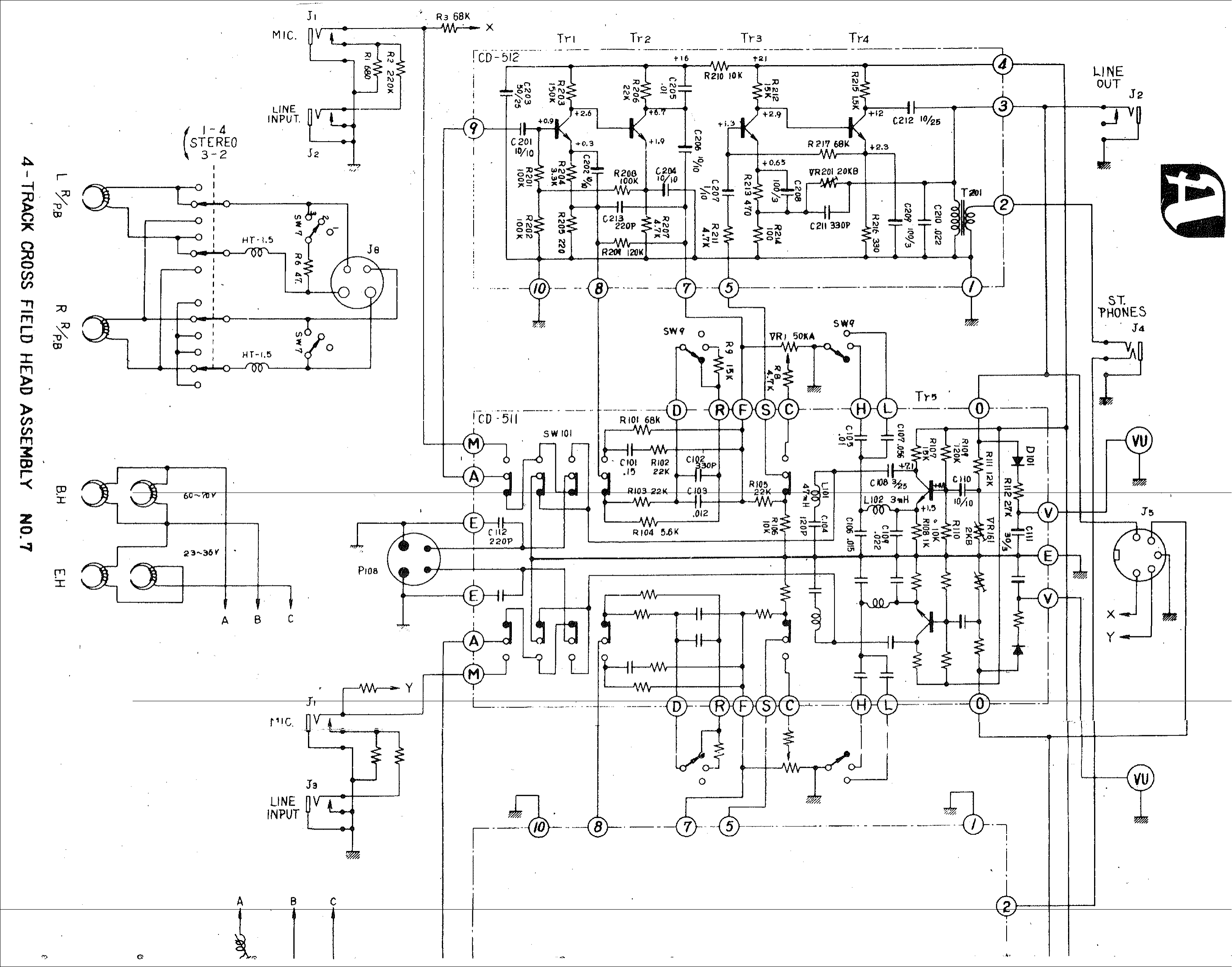 ⤢ zoomSchematic sheet 1: the four-track cross-field head assembly (No. 7) with its record/playback, bias, and erase head switching, feeding the CD-512 record/playback amplifier board (Tr1–Tr4) and the CD-511 board, wired to the microphone and line input jacks, line outputs, stereo phones jack, VU meters, and DIN connectors
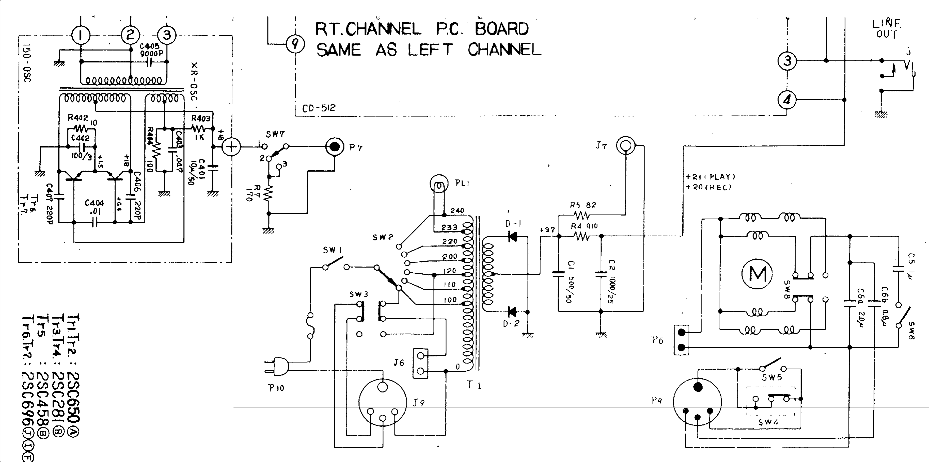 ⤢ zoomSchematic sheet 2: the bias oscillator section (XR-OSC and 150-OSC transformers, Tr6–Tr7), the power supply with its 100–240 V voltage-selector taps, rectifier diodes, pilot lamp, and motor circuit, plus the factory transistor-type list in the margin and a note that the right-channel P.C. board is the same as the left