Scan pages 3–6
Specifications, Measuring Method & Controls
I. Specifications
| Item | Value |
|---|---|
| STYLE | Portable |
| WEIGHT | 30.8 lbs (14.0 kg) |
| DIMENSIONS | 13-1/2" (H) × 13-1/2" (W) × 9" (D) 340 H × 340 W × 230 D mm |
| POWER SUPPLY | 100, 110, 120, 200, 220, 240 V.A.C. |
| RECORDING SYSTEM | Inline 4-track stereo, monaural playback. |
| TAPE SPEED | 3 speeds......1-7/8, 3-3/4 and 7-1/2 ips 15 ips optional |
| TAPE SPEED DEVIATION | Less than −1.5% at all tape speeds. |
| WOW AND FLUTTER (PLAYBACK ONLY) | Less than 0.15% R.M.S. at 7-1/2 ips. Less than 0.25% R.M.S. at 3-3/4 ips. Less than 0.35% R.M.S. at 1-7/8 ips. |
| FREQUENCY RESPONSE | 30 to 23,000 cps (Hz) at 7-1/2 ips. 30 to 18,000 cps (Hz) at 3-3/4 ips. 30 to 9,000 cps (Hz) at 1-7/8 ips. |
| SIGNAL TO NOISE RATIO | Better than 50 db. |
| DISTORTION (TOTAL HARMONICS) | Within 2% at 1,000 cps (Hz) [illegible]. |
| CROSS-TALK | Less than −65 db (Monaural) Less than −43 db (Stereo) |
| INSULATION RESISTANCE | More than 50 M.Ohms. |
| INSULATION DURABILITY | 1,000 V.A.C. for more than one minute duration. |
| ERASE RATIO | Less than −70 db for all tracks. |
| POWER CONSUMPTION | 55 VA |
| EQUALIZATION | Correct equalization for playback of tapes recorded to the NAB curve. |
| FAST FORWARD AND REWIND TIME | 90 seconds using 1,200 feet tape at 50 cps (Hz), 75 seconds at 60 cps (Hz). |
| OUTPUT LEVEL | 1.228 V (0 VU) at using 1,000 cps (Hz) 0 VU recorded tape. |
| OUTPUT IMPEDANCE | 1.5 K.Ohms |
| OUTPUT LEVEL OF STEREO HEADPHONE | 30~40 mV |
| OUTPUT IMPEDANCE OF STEREO HEADPHONE | 8 Ohms |
| INPUT LEVEL — LINE INPUT | 50 mV~2.5 V |
| MIC. INPUT | 0.5 mV~20 mV |
| DIN. INPUT | 20 mV~25 mV |
| MONITOR SYSTEM | Can be monitored the program being recorded by using. Stereo headphone (8 Ohms) ... Stereo headphone jack Crystal receiver ...... Line output jack. |
| MOTOR | Hysteresis synchronous 2-speed motor. Horse power : 1/100 HP Power ratio : 85% Revolution : 3,000 to 1,500 R.P.M. at 50 cps (Hz) 3,600 to 1,800 R.P.M. at 60 cps (Hz) Condenser capacity : 2.8 μF at 50 cps (Hz) 2.0 μF at 60 cps (Hz) |
| HEADS | |
| RECORDING/PLAYBACK HEAD | Inline 4-track stereo/monaural Gap ...... 0.2 microns Impedance ... 1,000 Ohms at 1,000 cps (Hz) |
| BIAS HEAD | Inline 4-track stereo Gap ...... 0.2 mm Impedance ...... 500 Ohms at 60 Kc |
| ERASE HEAD | Inline 4-track stereo. Gap ...... 0.2 mm Impedance ...... 300 Ohms at 60 Kc |
| RECORD LEVEL INDICATOR | Vertical indication Model "A" VU meter ×2 |
| TRANSISTOR USED | 2SC650 (A) ×4 2SC281 (B) ×4 2SC458 (B) ×2 2SC696 (J) (I) (F) |
| SILICON DIODE USED | SW-05-01 ×5 |
| REELS USED | 7", 5", 3" reels |
II. Measuring Method
Tape Speed Deviation
-
Method involving use of pre-recorded tape.
Playback on the tape recorder to be tested tape pre-recorded at 1,000 cps ±0.1% for measuring tape speed deviation. Connect the appropriate output to a frequency counter meter in order to measure the tape speed deviation from the resulting deviation of the measured frequency.
-
Method involving use of timing tape (designed for tape speed measurement).
This method utilizes a timing tape marked at intervals of 7-1/2". The running time of the tape over 60 marked section is measured in order to calculate the deviation of the tape speed. In application of this method, however, it should be borne in mind that should the timing tape stretch or contract, measurement error is inevitable, so that it is necessary to measure the total length of the tape in advance.
Wow and Flutter
Playback the 3,000 cps pre-recorded tape whose wow and flutter level is guaranteed to be smaller than 0.07% for measurement by means of a wow meter. It is also possible for a 3,000 cps sine wave to be recorded and played for measurement by means of the wow meter. In this case, however, the wow meter indicates a value as much as twice the value given in the specification on the first page.
Signal to Noise Ratio
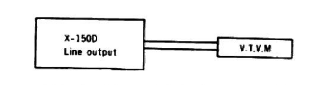 ⤢ zoomBlock diagram: X-150D line output connected to a V.T.V.M.
Set the Equalizer Switch on "7-1/2 ips" position and playback a tape containing a 1,000 cps sine wave recorded at "0" VU level on a standard recorder. Connect a V.T.V.M. to the line output jack of the recorder and measure its output.
Then remove the tape and measure the noise level under the same condition. Convert into decibels each of the measured values.
Total Harmonic Distortion Factor
 ⤢ zoomBlock diagram: audio oscillator, X-150D, and distortion meter connected in series
Connect the measuring instrument as shown above, and record the 1,000 cps sine wave at "0" VU. Playback the resultant signal and measure the overall distortion factor. Measure the noise level of the tape recorder with the tape removed: connect the audio oscillator directly to the distortion meter for measurement of the distortion factor of the oscillator.
The required distortion factor may be obtained from the results of the above measurement by the following formula.
d₀ = d − d₁ − d₂
where,
- d₀ = Required
- d = Overall distortion factor
- d₁ = Noise level
- d₂ = Distortion factor of the oscillator
(Note: New tape of particularly good quality should be used for measurement of the distortion factor).
Power Output
Playback a tape containing a sine wave of 1,000 cps recorded at 0 VU on a standard recorder.
Connect a V.T.V.M. to the line output jack of the recorder and measure the voltage at the output of the recorder to be tested.
Cross Talk (Cross talk between the tracks)
 ⤢ zoomDiagram of a tape showing tracks 1-4 in one direction and 4'-1' reversed, with the recorded, crosstalk, and no-input segments shaded
As shown in the figure, first record a 1,000 cps sine wave on track No. 3 at −3 VU level. Next, remove the 1,000 cps input signal and record under a non-input condition.
Then, playback the tape on track No. 3 and No. 1 (reversed condition of tape) through the 1,000 cps B.P.F. (Band Pass Filter, Sensitivity....1:1) and obtain a ratio between the two from the following formula.
C = 20 log [E₀ / (E₂ − E₁)] db
- C = Desired cross talk ratio (db)
- E₀ = 1,000 cps signal output level
- E₂ = 1,000 cps cross talk output level
- E₁ = No-input signal record level
Frequency Response
 ⤢ zoomBlock diagram: audio frequency oscillator, attenuator, X-150D line input/output, and V.T.V.M. connected in series
Connect the measuring instrument as in the above diagram, and measure the frequency response in the following sequence:
Record:
- Give a sine wave of 1,000 cps to the Line Input of the recorder to be tested through an attenuator from an audio frequency generator.
- Set the Record/Playback Knob in to "Rec" position and adjust the line input volume so that the VU meter needle indicates "0" VU.
- Under the condition described in (2), lower the input level 10 db by means of the attenuator.
- Record the spot frequency in the range of 30 cps to 25,000 cps from the audio frequency generator.
Playback:
- Set the Record/Playback Knob in to "Play" position.
- Set the Equalizer Switch on 7-1/2" or 3-3/4" position.
- Connect a V.T.V.M. to the Line output.
- Playback the tape previously recorded.
- Adjust the output level to "0" dbm at 1,000 cps as indicated on the V.T.V.M. by the range selecter of a V.T.V.M.
- Playback the recorded spot frequencies with the conditions in (9); make a memo of output level and plot the value on a graph.
III. Location of Controls
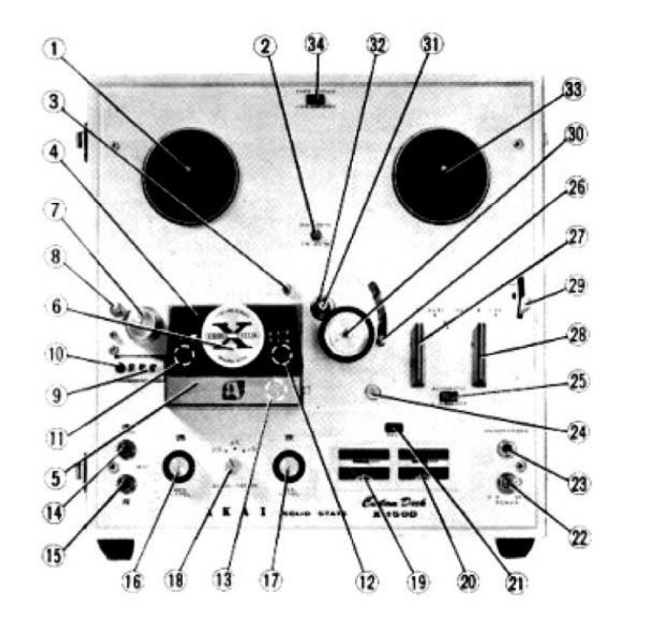 ⤢ zoomFront panel of the X-150D with numbered callouts 1 through 34
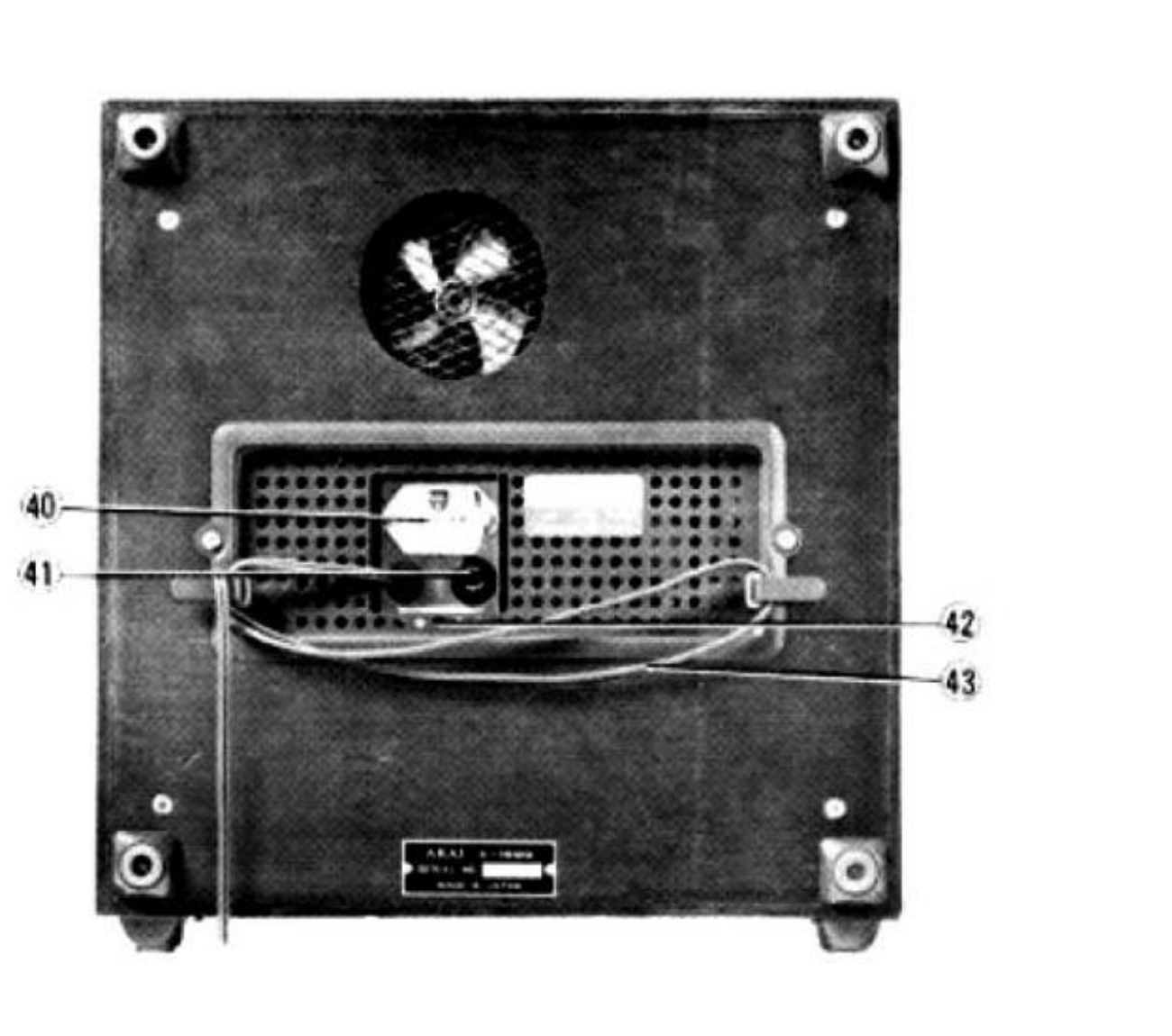 ⤢ zoomRear panel of the X-150D with numbered callouts 40 through 43
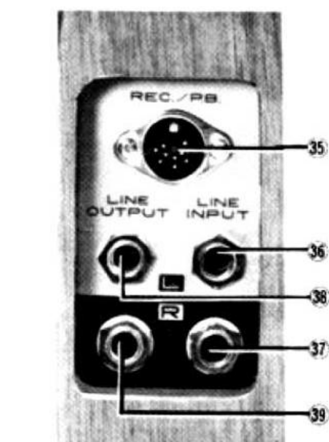 ⤢ zoomDIN and line input/output jack panel with numbered callouts 35 through 39
| # | Control |
|---|---|
| 1 | Supply Reel Shaft |
| 2 | Cycle Conversion Switch (A) |
| 3 | Capstan Storage Post |
| 4 | Head Cover (A) |
| 5 | Head Cover (B) |
| 6 | Track Selector Knob |
| 7 | Tape Guide |
| 8 | Tape Cleaner |
| 9 | Index Counter |
| 10 | Reset Button |
| 11 | Erase Head |
| 12 | Recording/Playback Head |
| 13 | Bias Head |
| 14 | Microphone Jack (Left) |
| 15 | Microphone Jack (Right) |
| 16 | Recording Level Control Knob (Left) |
| 17 | Recording Level Control Knob (Right) |
| 18 | Equalizer Knob |
| 19 | VU Meter (Left) |
| 20 | VU Meter (Right) |
| 21 | Recording Lamp |
| 22 | Power Switch |
| 23 | Stereo Headphone Jack |
| 24 | Recording Safety Button |
| 25 | AS Switch |
| 26 | AS Lever |
| 27 | Record/Playback Knob |
| 28 | Fast-Forward/Rewind Knob |
| 29 | Instant Stop Lever |
| 30 | Pinch Wheel |
| 31 | Capstan Shaft |
| 32 | Capstan |
| 33 | Take-Up Reel Shaft |
| 34 | Speed Change Switch |
| 35 | DIN Jack |
| 36 | Line Input Jack (Left) |
| 37 | Line Input Jack (Right) |
| 38 | Line Output Jack (Left) |
| 39 | Line Output Jack (Right) |
| 40 | Voltage Conversion Switch |
| 41 | Fuse Post |
| 42 | Cycle Conversion Switch (B) |
| 43 | AC Cord |