Scan pages 3–10
General Information
I.1. Specifications
| Tape Speed | 3 speeds — 1-7/8, 3-3/4 and 7-1/2 ips (15 ips optional) |
| Wow and Flutter | Less than 0.12% RMS at 7-1/2 ips |
| Less than 0.15% RMS at 3-3/4 ips | |
| Less than 0.20% RMS at 1-7/8 ips | |
| Frequency Response | 30 to 23,000 cps ±3 db at 7-1/2 ips |
| 30 to 18,000 cps ±3 db at 3-3/4 ips | |
| 30 to 9,000 cps ±3 db at 1-7/8 ips | |
| Signal to Noise Ratio | Better than 50 db |
| Input Level | Mic — more than 0.5 mV |
| Line — more than 60 mV | |
| Output Level | 0 VU (1.23 V RMS) |
| Equalization | Correct equalization for playback of tapes recorded to the NAB curve. |
| Recording Bias Frequency | 60 kc |
| Recording Level Indicator | VU meter × 2 |
| Recording System | CROSS-FIELD bias system, 4-track stereo/monaural system |
| Fast Forward and Rewind Time | 90 seconds using 1,200 feet tape at 50 cycles. |
| 75 seconds at 60 cycles. | |
| Maximum Recording Time | 8 hours monaural recording at 1-7/8 ips (1,200 feet recording tape). |
| 4 hours stereo recording at 1-7/8 ips | |
| Head | Recording/playback head — 4-track stereo/monaural, low impedance 1,000 ohms at 1,000 cps |
| Bias head — 4-track stereo, low impedance 500 ohms at 60 kc. | |
| Erase head — 4-track stereo, low impedance 300 ohms at 60 kc. | |
| Motor | Hysteresis synchronous 2-speed motor |
| Transistor | Silicon transistor × 11 |
| Diode × 2 | |
| Rectifier × 2 | |
| Power Supply | AC 100 to 240 V, 50/60 cycles |
| Power Consumption | 55 VA |
| Dimensions | 13-1/2″ H × 13-1/2″ W × 9″ D (340 H × 340 W × 230 D mm) |
| Weight | 30.8 lbs (14.0 kg) |
I.2. Controls
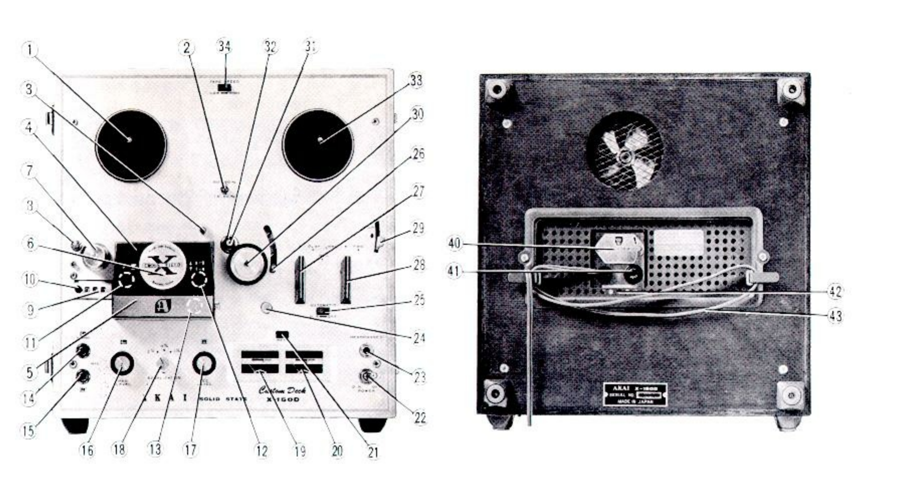 ⤢ zoomControls callout photographs: the X-150D from the front with numbered leader lines 1 through 34 marking the deck-panel controls, and from the rear with callouts 40 through 43 marking the voltage-conversion hatch, fuse post, and AC cord
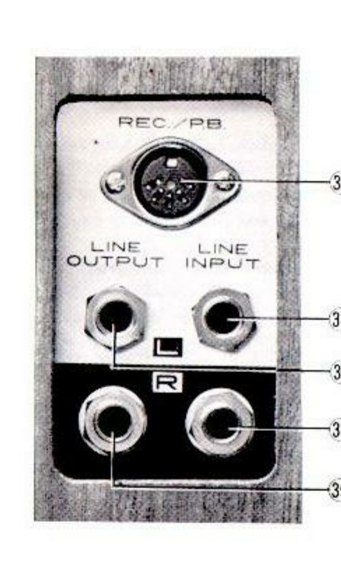 ⤢ zoomJack panel photograph: the REC./PB. DIN jack above the LINE OUTPUT and LINE INPUT jack pairs, L row above R row, with callouts 35 through 39
- Supply Reel Shaft
- Cycle Conversion Switch (A)
- Capstan Storage Post
- Head Cover (A)
- Head Cover (B)
- Track Selector Knob
- Tape Guide
- Tape Cleaner
- Index Counter
- Reset Button
- Erase Head
- Recording/Playback Head
- Bias Head
- Microphone Jack (Left)
- Microphone Jack (Right)
- Recording Level Control Knob (Left)
- Recording Level Control Knob (Right)
- Equalizer Knob
- VU Meter (Left)
- VU Meter (Right)
- Recording Lamp
- Power Switch
- Stereo Headphone Jack
- Recording Safety Button
- Automatic Shut off (AS) Switch
- Automatic Shut off (AS) Lever
- Record/Playback Knob
- Fast-Forward/Rewind Knob
- Instant Stop Lever
- Pinch Wheel
- Capstan Shaft
- Capstan
- Take-Up Reel Shaft
- Speed Change Switch
- DIN Jack
- Line Input Jack (Left)
- Line Input Jack (Right)
- Line Output Jack (Left)
- Line Output Jack (Right)
- Voltage Conversion Switch
- Fuse Post
- Cycle Conversion Switch (B)
- AC Cord
I.3. Cross-Field Head
The cross-field head created a sensation in the tape recorder market by making possible a wide range recording never before heard on any conventional tape recorder.
Using this cross-field head, Model X-150D provides a surprising recording performance of 30-23,000 cps at a tape speed of 7-1/2 ips, 30-18,000 cps at 3-3/4 ips and 30 to 9,000 cps at 1-7/8 ips.
What is superior about cross-field recording? How does it differ from typical recording methods as far as construction is concerned? On these, explanation is given below in sequences:
In the typical recording system, the signal current and the bias current are combined together and applied to the recording head. (Refer to Diagram 1.)
It is well known that the purpose of bias current is to record, at high sensitivity, a signal applied on the tape, with little distortion and minimizing noise generation.
However, the bias current providing such an advantage also has an undesirable character. That is, the wide magnetic field of the bias current affects the recorded signal, resulting in weakening or even erasing the signal. This phenomenon is particularly noticeable at high frequencies.
In the cross-field system, the signal current is applied to the recording head while the bias current is applied to the bias head.
These two heads are located in different positions, as determined inter-relatively, so that the magnetic field of the bias will not affect the signal recorded on the tape, even when sufficient bias is applied. This allows the recorded signal to remain on the tape with high fidelity.
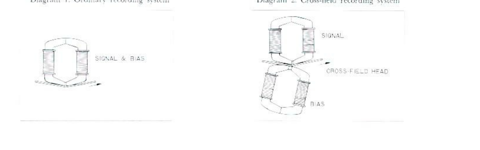 ⤢ zoomDiagram 1, Ordinary recording system: a single head carrying signal and bias together; Diagram 2, Cross-field recording system: separate signal and bias head windings meeting the tape from opposite sides at the cross-field head
I.4. Recording/Playback for 4-Track
The Model X-150D employs the 4-track system, either stereo or monaural.
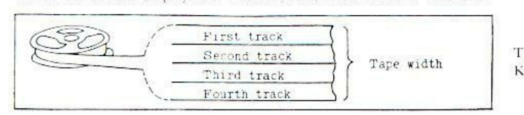 ⤢ zoomTrack layout diagram: a reel feeding tape divided lengthwise into first, second, third, and fourth tracks across the tape width
Track selection is made by the TRACK SELECTOR KNOB (6).
(A) Recording/Playback for 4-Track Stereo
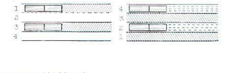
For stereophonic recording two of these tracks are used at a time. Set the TRACK SELECTOR KNOB (6) in "STEREO" position. The first half of stereophonic recording/playback is made on Tracks No. 1 and 3 and the second half on Tracks No. 2 and 4 after the tape reels have been turned over.
 ⤢ zoomStereo track diagram: tracks 1 and 3 recorded on the first pass, tracks 2 and 4 on the second pass after the reels are turned over
(B) Recording/Playback for 4-Track Monaural
Recording/Playback of monaural should be performed in the sequence of 1-4-3-2 (tracks).
- Monaural recording/playback on tracks No. 1-4 — Set the TRACK SELECTOR KNOB (6) to "1-4" for recording on track No. 1 first, and then on track No. 4 after the tape reels have been turned over.
- Monaural recording/playback on tracks No. 3-2 — Set the TRACK SELECTOR KNOB (6) to "3-2" for recording on track No. 3 first, and on track No. 2 after the tape reels have been turned over.
 ⤢ zoomMonaural sequence diagram: four tape passes marked 1, 4, 3, 2 at the recording head, the reels turned over between passes, with the tape transport direction arrowed
I.5. Operational Precautions
IMPORTANT: READ THE FOLLOWING INSTRUCTIONS CAREFULLY BEFORE OPERATING YOUR MACHINE:
- THE USE OF NEW TAPE WILL RESULT IN THE BEST RECORDINGS.
- THE SYMPTOMS LISTED BELOW DO NOT NECESSARILY INDICATE MECHANICAL
FAILURE OF YOUR TAPE DECK. IF YOUR MACHINE EXHIBITS ANY OF THESE
SYMPTOMS, CHECK FOR THE TROUBLE AS INDICATED
- Loss of sensitivity and tone quality may be due to:
- A. Dirty erase head. This will prevent prerecorded material from being completely erased.
- B. Dust on the recording head. Clean the head gently with a soft cotton swab soaked in rubbing alcohol or carbon tetrachloride.
- C. A.C. power voltage lower than the standard voltage to which your machine is adjusted.
- Irregularity in the tape transport may be due to:
- A. Grime adhering to the heads.
- B. Oil on the capstan.
- C. Sticky or dirty tape surface.
- D. Bent take-up reel.
- If your machine will not record, check the following for correct
position.
- A. Record/Playback knob.
- B. Input plugs.
- Loss of sensitivity and tone quality may be due to:
Note:
- Before operating your machine, be sure to clean the surface of the head.
- Unused tape may become soft and sticky. It is advisable to run the tape once from the supply reel to the take-up reel before threading it for recording.
3. THE FOLLOWING NOTES ARE PROVIDED FOR YOUR CONVENIENCE.
- (A) If any trouble develops, please take your machine to the nearest authorized agent in your area or inquire at the Service Dept. of the Akai Company in Tokyo, Japan.
- (B) Your Akai Tape Deck Model X-150D requires constant voltage for optimum performance.
- (C) The standard 1,200 feet length of tape on a 7″ reel plays up to 32 minutes at 7-1/2 ips in one direction.
- (D) If the sound sources are so far away from the microphones that the volume control must be turned up to a maximum, some hum or noise will inevitably be recorded. In such instance, a test recording is recommended before attempting a final recording.
I.6. Voltage and Cycle Conversion
Power Voltage Adjustment
The Model X-150D is operatable anywhere in the world. With the built-in stepdown power transformer, the user can easily readjust the recorder to any one of the six stages of power voltage from 100 to 240 volts A.C. Generally, the recorder's input voltage is preset for the forwarding territory.
The user is requested to check the previously set voltage before operation. This can be seen at the rear of the recorder.
If another voltage is required, readjusting of the voltage can be made in accordance with the following instructions.
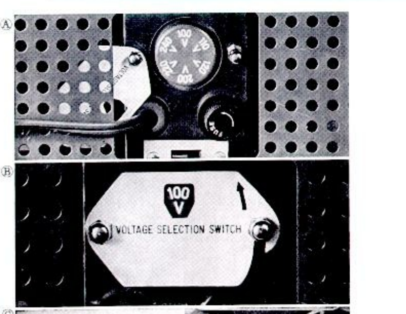
- Take off the cover panel by removing two mounting screws as shown in Fig. A. Then, pull out the VOLTAGE CONVERSION SWITCH (40) gently and reset the knob so that the desired voltage will appear on the panel. (See Fig. B)
- The voltage conversion switch is a plug-in type movable in six steps, 100/110/120/200/220/240. For example, if the power voltage distributed in your area is 220 volts A.C., reset the switch to 220 mark.
- Change fuse according to voltage. Fuse: 100V
120V 0.8A, 200V240V 0.4A
CAUTION: Disconnect the power plug from the AC outlet before readjusting power voltage. To maintain optimum performance and to prolong the life of your machine, it is important that the line voltage be held within 10 percent deviations from the standard voltage.
 ⤢ zoomFigures A and B: the rear hatch of the recorder with the voltage dial visible behind the cover panel, and the plug-in VOLTAGE SELECTION SWITCH pulled out and set to 100 V
Power Cycle Change
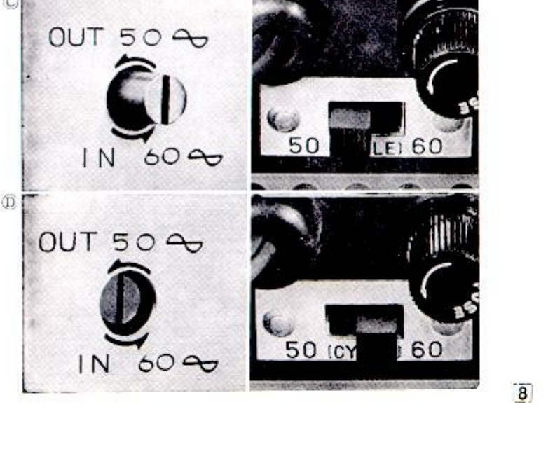
Correct tape speed is not obtainable if the CYCLE CONVERSION SWITCHES are not properly adjusted. The CYCLE CONVERSION SWITCH (A) (2) is located at the center of the deck top panel and the CYCLE CONVERSION SWITCH (B) (42) at the rear of the recorder. Using a screw driver, rotate the CYCLE CONVERSION SWITCH (A) (2) counter clockwise approximately one-eighth of a turn. The switch can then be moved either OUT or IN. 50 cycle operation is obtained by moving the switch OUT (Fig. C), and 60 cycle operation, by the switch IN (Fig. D). The switch (2) should be rotated back to its original position after it has been moved either OUT or IN. The CYCLE CONVERSION SWITCH (B) (42) should also be reset.
CAUTION: Do not attempt to rotate the CYCLE CONVERSION SWITCHES when the motor is not running.
 ⤢ zoomFigures C and D: the deck-top cycle conversion switch in its OUT 50-cycle and IN 60-cycle positions, alongside the rear slide switch moved between its 50 and 60 marks
I.7. Selection of Tape Speeds
| Tape Speed (ips) | Speed Change Switch LOW | Speed Change Switch HIGH | Capstan Bushing YES | Capstan Bushing NO | Use |
|---|---|---|---|---|---|
| 1-7/8 | ○ | ○ | Long time recording of Jazz, Speech, Lecture, etc. | ||
| 3-3/4 | ○ | ○ | High fidelity recording of Popular or Classical music, etc. | ||
| 7-1/2 | ○ | ○ | Recording music with max. clarity, Playback of pre-recorded tape. |
The X-150D operates usually on 3 tape speeds, 7-1/2, 3-3/4 and 1-7/8 ips. Refer to the chart above for selecting an adequate tape speed. Tape speed is determined by the motor speed and by the capstan bushing on the tape drive capstan shaft.
- 1-7/8 ips. This tape speed is obtained by setting the SPEED CHANGE SWITCH (34) to "LOW". The capstan bushing is not used but is left on the storage post.
- 3-3/4 ips. This tape speed is obtained by setting the SPEED CHANGE SWITCH (34) also in "LOW" position. The capstan bushing is mounted on the capstan shaft and is locked automatically in position by the notches.
- 7-1/2 ips. This tape speed is obtained by setting the SPEED CHANGE SWITCH (34) in "HIGH" position. The capstan bushing is used. 15 ips tape speed is also available by using an extra capstan and a pinch wheel which are optional.
RECORDING TIME
| Tape Length | 1-7/8 | 3-3/4 | 7-1/2 |
|---|---|---|---|
| 4-Track Stereo | |||
| 1200 ft | 4 hrs | 2 | 1 |
| 1800 | 6 | 3 | 1.5 |
| 2400 | 8 | 4 | 2 |
| 4-Track Mono | |||
| 1200 | 8 | 4 | 2 |
| 1800 | 12 | 6 | 3 |
| 2400 | 16 | 8 | 4 |
 ⤢ zoomCapstan photograph: the deck top with leader lines marking the capstan bushing, the capstan storage post, and the speed change switch