Scan pages 16–21
Operating Instructions: Maintenance & Connections
II.10. Monaural Playback
- (A) Set the POWER SWITCH (22) to "ON".
- (B) Set the TRACK SELECTOR KNOB (6) to "1-4".
- (C) Select the tape speed as desired.
- (D) Set the EQUALIZER KNOB (18) to 7-1/2, 3-3/4 or 1-7/8, whichever is consistent with tape speed.
Place the pre-recorded tape on the tape deck.
On monaural playback, only the left channel amplifier should be used.
- (E) Connect LINE OUTPUT JACK (LEFT) (38) to TAPE INPUT or AUX INPUT JACK of an external amplifier. Also connect the loud speaker to the power amplifier.
- (F) Set the RECORD/PLAYBACK KNOB (27) to "PLAY".
After completing monaural playback on track No. 1 and No. 4, set the TRACK SELECTOR KNOB (6) to "3-2" for continuing with track No. 3, then track No. 2.
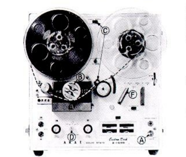 ⤢ zoomMonaural playback: the deck front with letters A through F marking the controls in order
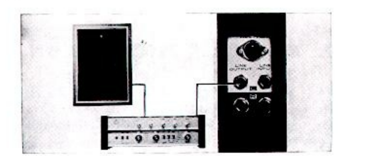 ⤢ zoomMonaural playback connections: the left line output wired through an external amplifier to a single loudspeaker
II.11. Tape Erasing
Any signal information previously recorded on a tape will be erased automatically as a new recording is made on the same tape. Thread the tape, and place in normal record position. There should be no plugs connected to recorder's input jacks. RECORDING LEVEL CONTROL KNOBS (16) and (17) should be held in "0" position. A BULK TAPE ERASER is recommended for quick and complete erasure.
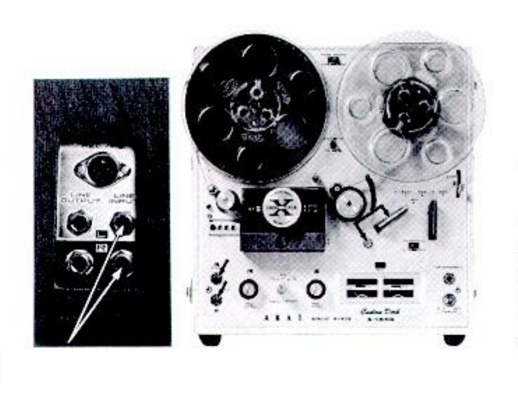 ⤢ zoomTape erasing: the jack panel with arrows marking the input jacks left empty, beside the deck threaded in record position
II.12. Fast Forward and Rewind
Fast forward or rewind is accomplished by turning the FAST FORWARD/REWIND KNOB (28) into the proper position. Put the tape in fast forward or rewind for rapid selection of the recordings on the tape. The FAST FORWARD/REWIND KNOB (28) cannot be turned out of the stop position unless the RECORD/PLAYBACK KNOB (27) is in stop position, and vice-versa.
II.13. Monitoring
Monitoring is made by connecting the stereo headphone to the STEREO HEADPHONE JACK (23).
On monaural as well as stereo recording, please use of the stereo headphone.
Caution: The stereo headphone should be of low impedance type (8 ohms).
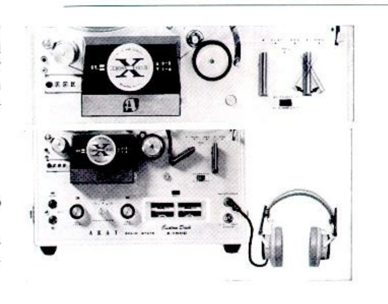 ⤢ zoomFast forward/rewind and monitoring: two deck photographs — the fast-forward/rewind knob turned with the tape path shown, and stereo headphones plugged into the headphone jack
II.14. Tape Splicing and Editing
Superimpose the tapes and cut them diagonally as illustrated. (This diagonal cutting eliminates the "click" or "pop" sound of the splice.)
Register the cut ends and apply a splicing tape on the glossy side of the record tape.
Press the splice tape with fingers firmly to secure the ends evenly. Trim off excess splicing tape. Preferably, cut the recording tape slightly along its edge as illustrated by the dotted line. This eliminates the possibility of a sticky splice. Tape splicing using scissors requires skillful work. The scissors should not be magnetized. But, our specially designed portable splicer can do the job with ease.
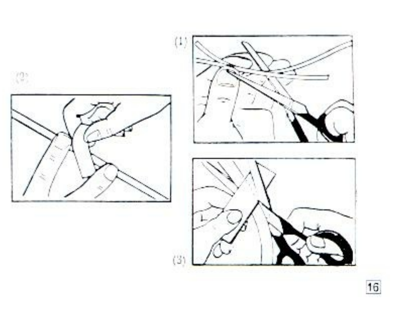 ⤢ zoomTape splicing: three drawings numbered 1 to 3 — the tapes superimposed and cut diagonally with scissors, the splice pressed by hand, and the edge trimmed along the dotted line
 ⤢ zoomThe portable splicer between two reels of tape
II.15. Cleaning Head
TAPE OXIDE DEPOSITS ARE 90% OF CAUSES OF THE YOUR TAPE RECORDING FAILURES.
It is imperative for quality performance of a tape recorder to keep the heads neat and clean at all times.
Dust and magnetic particles from the tape tend to deposit on the heads after prolonged use of the tape recorder. This would result in poor head-to-tape contact, deteriorating sound quality and sensitivity.
Such dust would cause a significant drop in recording, playback and erase quality levels.
EXAMPLE
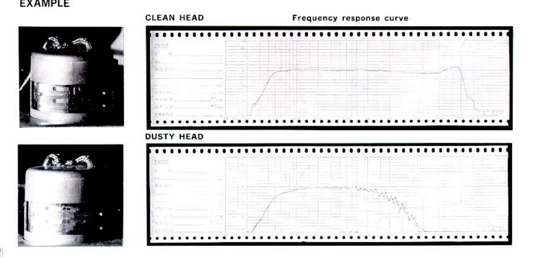 ⤢ zoomClean head versus dusty head: photographs of the head block clean and dusty, each beside its measured frequency response curve — flat for the clean head, collapsing at high frequencies for the dusty head
Make it a rule to clean the heads every time you use your tape recorder. AKAI's Head Cleaning Kit (Accessory No. HC-500) is recommended for removing foreign matter deposited on the heads. If this kit is not available, use alcohol.
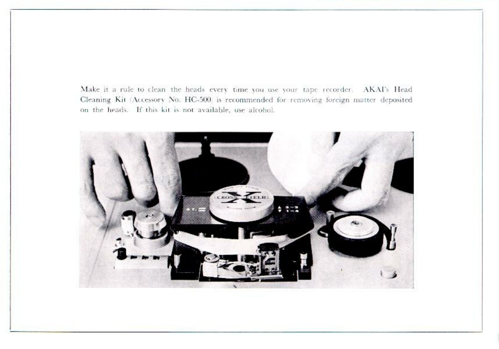 ⤢ zoomFull-page photograph, manual page 18: two hands cleaning the head block with a swab, the head cover removed and resting beside the deck
II.16. Head Demagnetization
Normally, the steel pole pieces which form a part of the recording and playback heads become slightly magnetized. The effect of the slight head magnetization is to partially erase the tape. Mostly high frequencies suffer. Generally, slightly magnetized heads can be detected by noticing loss of normal high frequency response which cannot be corrected through head alignment. Severe magnetization which may result if magnetized tools are used in the vicinity of the heads will result in noise or considerable distortion in addition to the loss of high frequency response. Although the X-150D already has a built-in Head Demagnetizing circuit, it is recommended that head demagnetization be performed periodically.
After removing the head cover, head demagnetization can be accomplished by touching the head lightly with the demagnetizer and making several small circular motions over all head surface areas as well as the head housing.
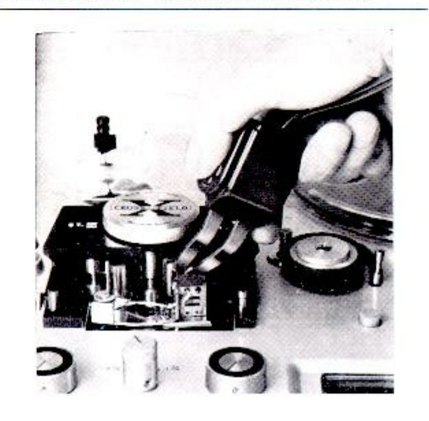 ⤢ zoomHead demagnetization photograph: the demagnetizer held against the exposed head block, the head cover removed
II.17. Tape Duplication
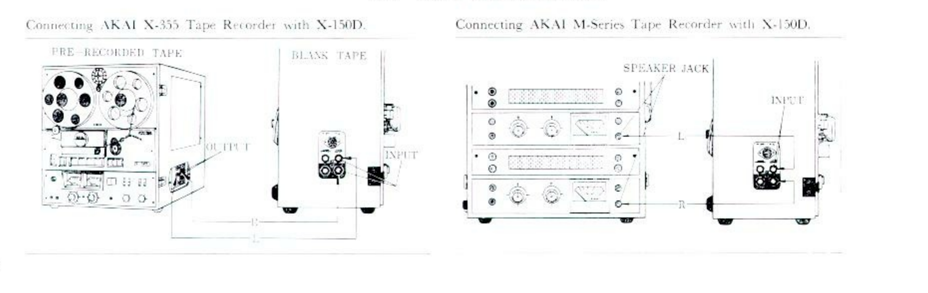 ⤢ zoomTape duplication diagrams: connecting an AKAI X-355 tape recorder with the X-150D, pre-recorded tape to blank tape via output and input jacks, and connecting AKAI M-series tape recorders with the X-150D through their speaker jacks to the recorder input
II.18. DIN (One Multiple-Connection) Jack
 ⤢ zoomDIN jack pinout: a front view of the five-pin DIN jack with leader lines reading GROUND (common to both channels), PREAMP OUTPUT (left channel-recorder), PREAMP OUTPUT (right channel-recorder), GROUND (same as number 8 above), REC INPUT (right channel-ext. amp), and REC INPUT (left channel-ext. amp)
The DIN JACK is provided on the right side of the X-150D for interconnecting the X-150D with an external stereo amplifier that has the same connection jack. This system will permit easy recording and playback of stereophonic programs through an external stereo amplifier as the complexity of connecting or disconnecting more than 4 separate plugs from the recorder's panel side is not needed.
If your amplifier is not equipped with the DIN jack and the use of this one connection system is required, consult a radio engineer for the necessary modification of your amplifier.
II.19. Ventilation
The Model X-150D has a unique ventilation system. It is so designed that air circulation inside of the unit is properly maintained at all times and no excessive heat which would shorten the life of the component parts is developed. Although the X-150D is tropicalized in construction, it is recommended that the unit always be spaced a short distance apart from a wall, screen, or any other obstacle which might prevent good air circulation around the unit.